As stated previously, instead of dedicating each post for one module, I’ll combine the ones with similar techniques into one post. And as expected, this proved to be harder than I thought.
The first set covers modules with transparent and emissive surfaces: cockpit, generator and reactor. I deliberately left out many technical details that are handled in the previous chapters. Hopefully things don't get too messy.
Requirements
Bloom effect is easily overused, so I'll be sparing strong emissive values for informational use only. Previously they were used for indicating the player color, and other use cases will be constrained to cockpit and energy sources, them being the most important module types.
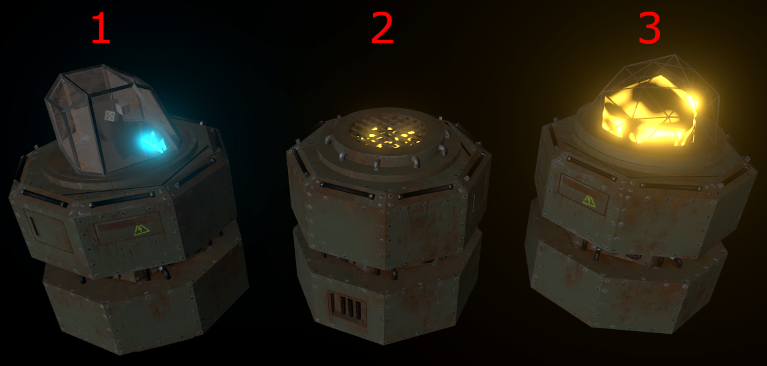
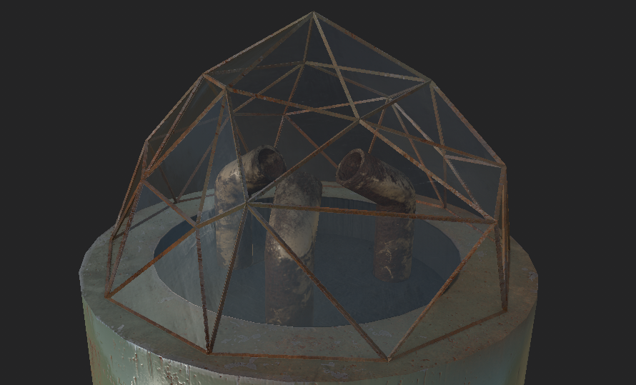
Cockpit (1) is the centerpiece of the ship: lose it, and you’ll lose the game. As a main target, it should be easily distinctive. The model itself is basically a framed glass dome with an irritatingly bright flight deck and an uncomfortable seat.
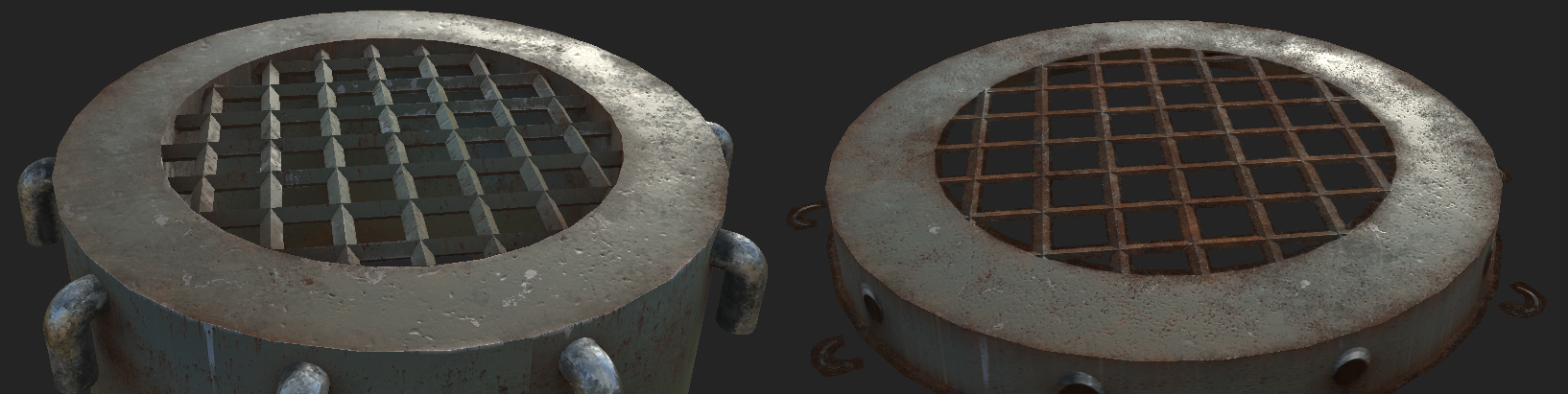
Generators (2) and reactors (3) supply energy for the ship. Energy is an important game concept that players should be constantly aware of; nearly every functionality consumes it, and overheating may blow up the sources causing collateral damage. Level of the glow indicates the ship's energy consumption, and overheating makes things especially bright in order to warn the player.
Reactor's energy is obtained from a lump of some kind of glowing, unstable substance. It is created by spraying together three materials, each of which is stored separately for safety reasons. A twisted glass dome with metal framing prevents the stuff from escaping. Generators produce less energy, but are more stable. They don’t need glass surfaces, a grid covering the energy source suffices.
Instead of using three LOD levels as in the previous chapters, I found two to be enough. Base model, connectors and module-specific geometry are separate entities, so they can have any number of LOD models independently from each other. And as there is only one cockpit per ship, no LOD models are needed for it at all.
Modelling
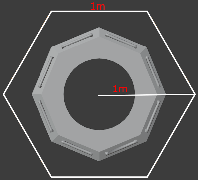
For starters, a thing I have previously forgotten to mention: the scale. Hex tile's circumradius (distance from the center to one of its six points) is exactly one meter, which means that each edge is also equally long.
New module types required some improvements to my reference models:
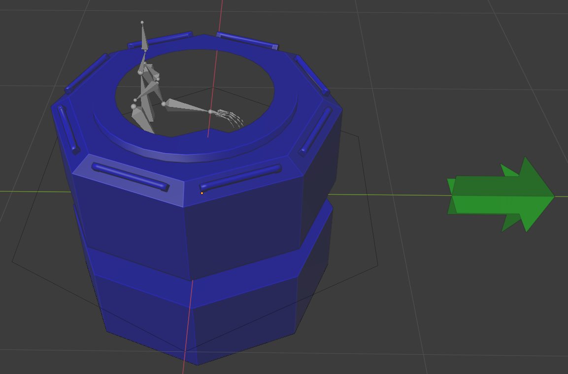
- The medium-poly model is used as a module base reference (shown blue in a screenshot below). All the additional parts are built on top of it. The base itself will not be exported with the module-specific parts. Instead, parts are added into the previously created prefab in Unity (more about this later).
- So far the models have been quite symmetrical, but from now on it gets increasingly important to orient them properly. This is especially crucial with aimed and animated modules that will be handled in the following chapters. I created a reference arrow to tell the forward direction (green).
- The base module should be able to fit in the pilot, so I used Blender’s skeleton model as a reference (grey).
Most of the opaque parts are modelled with cylinders and pipes as in the previous chapters, so nothing too fancy there. I made a simple bottom part for each module, so that they can be rendered from below if needed. Texture space is naturally prioritized for up-facing surfaces. Below are the exported hi-poly models without the module base.
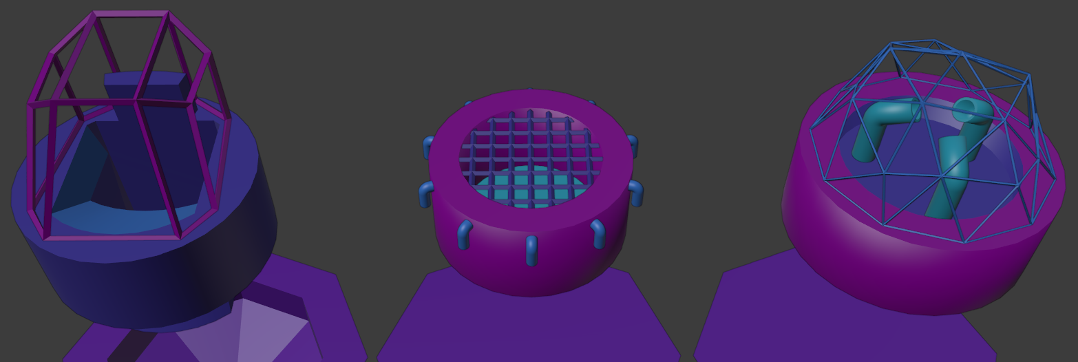
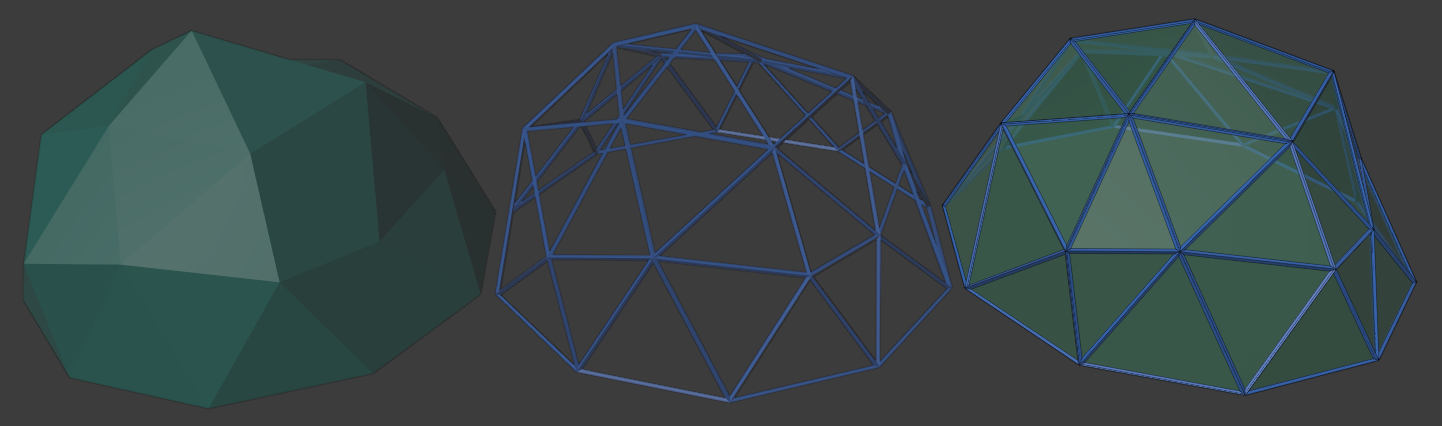
For the translucent reactor dome, I started with a half-spherish object to model the glass (on the left). In order to create the frame geometry, I duplicated it and added a wireframe modifier (center). Object on the right shows how the two look together. Cockpit dome is done similarly. Low-poly models don't have the frame object. They only need the dome, as frame geometry will be baked onto it in Substance (further details in texturing part).
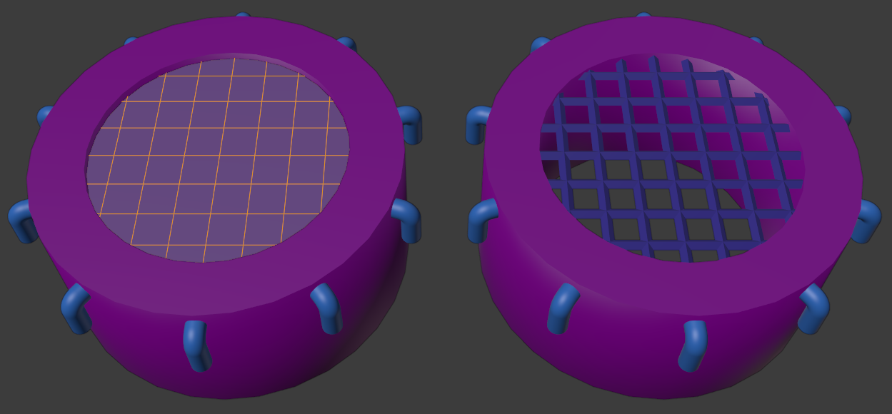
Generator doesn't have translucent parts, but the grid is created with a wireframe -modifier. Instead of a dome polyhedron, I created a quad and subdivided it until I had the grid I wanted (results below). Low-poly model of a generator is just a fat solid cylinder with the grid baked onto its texture.
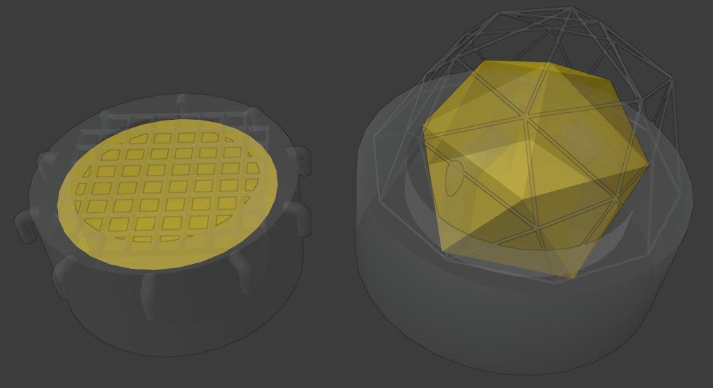
The glowing energy substances will be rendered with a custom shader and material, so their objects are exported separately. Generator's object is just a circle below the grid, while the reactor uses a polyhedron (shown in yellow).
Texturing the opaque parts
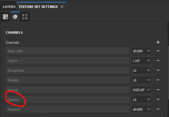
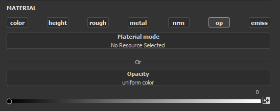
Cockpit and reactor have both translucent and opaque parts and in order to handle all parts in a single Substance-project, it is best to use "PBR - Metallic Roughness Alpha-blend" -template. This way backface culling will be disabled and translucency is properly rendered. If the opacity/translucency-channel doesn't already exist, it can be created by pressing the "+"-button in the "Channels"-section and selecting "Opacity". Cockpit's flight deck also needs an emissive channel.
Separate texture sets are created for each LOD model and the glass object. This way glass can be textured separately from opaque parts and re-used for both lo- and hi-poly models. Base material is almost identical to the one we used before. Cockpit's interior is black to make the glow clearly visible. Reactor's pipes and hearth should look burned and severely damaged.
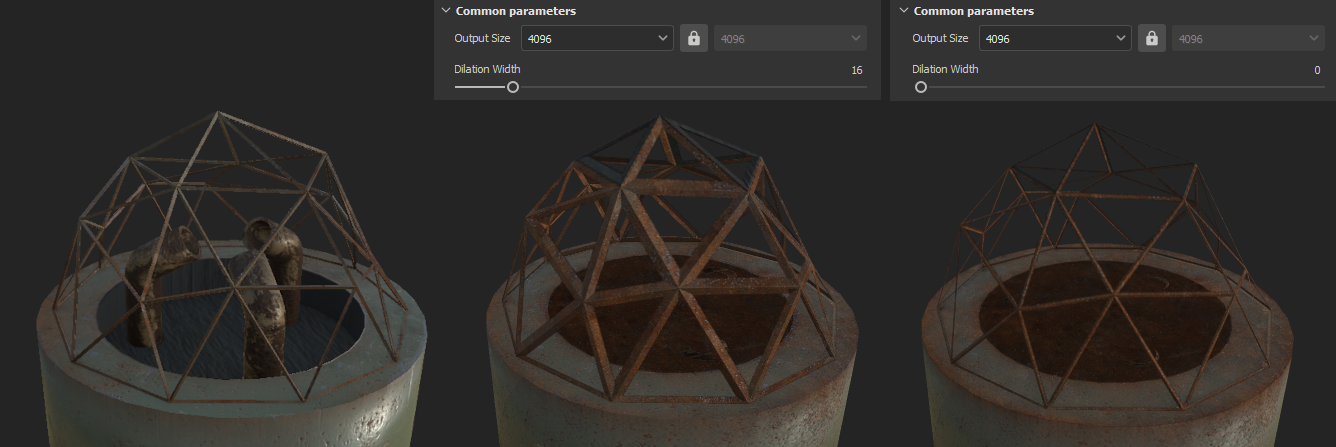
As said previously, frame geometry is not included in the low-poly models, but baked instead. The image below shows the result. On the left is the hi-poly model with all the geometry, while the two others visualize the geometry baked onto the dome texture. While baking, I ran into a problem where the baked frames became thicker than they should be (center). The solution was to decrease "Dilation Width" in baking settings. Results with dilation widths 16 and 0 are shown. Be aware that dilation is relative to the "Output Size"-value.
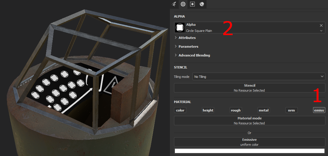
For the flight deck emissions I added a new layer, deactivated all but emission channel ("emiss") from it (1) and then just stamped various shapes from the alpha-selection (2) all over the deck. As the emissive parts are strongly bloomed, the details won't be distinguished in a game.
Texturing the translucent parts
From the very start, I knew that the cockpit windows should be extremely dirty, only having a small wiped area for peeking out. Poor visibility also works as an excuse for all the AI issues.
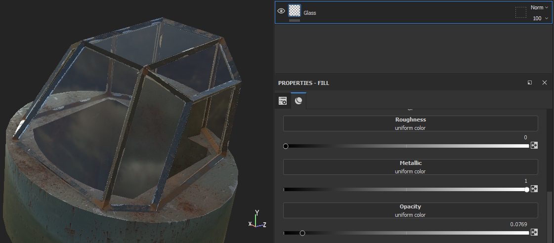
I first created a fill layer "Glass" and gave it little opacity so it isn't completely invisible. Minimum roughness and maximum metallic values make it flawlessly smooth and reflecting.
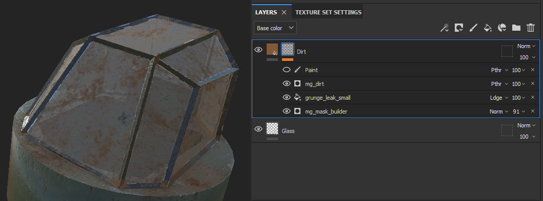
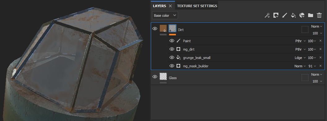
The dirt I made by using Substance's generators. I won't go deeper with them, as the texturing was originally made with an older version of Substance, and some of the used generators seem to be deprecated nowadays. You'll probably find better ones from the built-in smart materials. The image below shows my generator stack and its result.
Now the glass sure looks dirty but since the poor pilot cannot see outside, something must be done. I added a paint mask on top of "Dirt"-layer, set its type to pass-through ("Pthr") and wiped the window with smudge-tool (found in the toolbox on the left side of the Substance-window). It took quite much trial and error to make mask settings work, but the image below shows how I succeeded. This was probably the first time I found a proper use for a smudge tool in any software.
Reactor's glass dome is practically identical, but much more subtle dirt/scratch generators are used. This way the energy glow is clearly visible during the game.
Alpha testing
As the generator has no translucent parts, I used "BPR - Metallic Roughness Alpha-test" template. It makes sure the surfaces only have fully opaque and transparent areas, never anything between them.
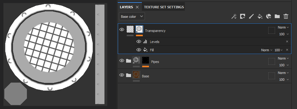
As with the previous models, I textured the hi-poly model first and copied materials onto low-poly object. For the transparency, I first added new fill layer "Transparency" as the top layer. I deselected all channels but opacity ("op") and changed its value to zero. The model should now be completely painted with transparency, and thus disappear from the view.
To find the parts that need to be seen, I added a bitmap mask to the layer (right click the layer and select "Add bitmap mask"). I selected an ID map as a mask, but ambient occlusion map could work also; this depends on the model. Light parts of the mask texture become transparent, so the mask needs to be inverted (right click the mask and select "Invert mask"). Now all the parts that should be transparent become lighter in mask view and disappear from the model. Inversion automatically adds a "Levels" mask that you can use to adjust the opacity. You can also stack other masks and filter out areas by color ID or by painting. Tip: mask is set visible by alt-clicking its icon (on the left side of the layer name).
On the left below is the high-poly model with its grid modelled as a geometry. On the right side is the baked low-poly model. Grid colors/rust differ a little and could be made more similar by tweaking the layer effects. But most of the time there will be a fire (or something) burning beneath the grid, so the difference is hardly noticeable.
Substance exports transparency in albedo-texture's alpha-channel. As reactor and cockpit were textured by using alpha-blending template, their low-poly alpha values vary from zero to one. Generator's alpha values are strictly zero or one.
Importing transparent materials to Unity
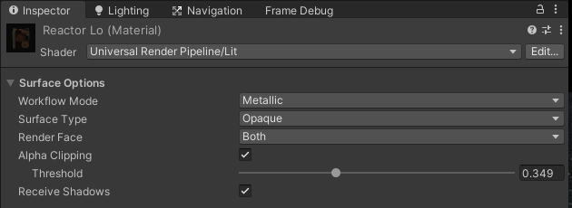
The handling of translucent and opaque materials differs a bit in Unity: glass surface should use transparent surface type with alpha blending, while baked geometry uses opaque surface with alpha clipping. Hi-poly geometry uses normal opaque material without clipping.
Difference between opaque and transparent mode is that opaque will not use blending. Setting "Alpha Clipping" forces alpha values to either zero (below threshold value) or one. Clipping should be used instead of blending even if the alpha channel already contains only ones and zeros; Unity uses it for optimizing draw order and depth-buffering. Transparent shaders use gradient alpha values for various types of blending. I'll be using the most common "Alpha" -mode.
While rendering a transparent or alpha-clipped object, it is usually a good idea to turn off backface culling (set "Render Face" to "Both"). This way also the backward-facing parts of the lo-poly dome become visible.
If you're having problems with Unity's two-sided lighting, you can duplicate the glass model in Blender and flip its normals ("Mesh" -> "Normals" -> "Flip" in edit mode for the duplicated mesh). Then just export both models and render them on top of each other with the same material, but "Render Face" set to "Front".
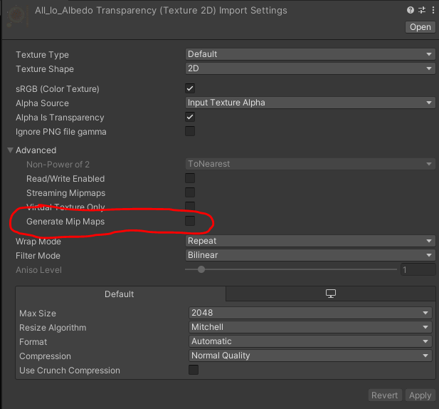
The cosmetic issues I met were mostly solved by experimenting, but I also ran into a harder problem with generator's alpha clipping: with the lower mipmap levels (used when the object gets small) the transparent areas of the grid got blurred and lost their transparency. Enabling "Mip Maps Preserve Coverage" and adjusting its "Alpha Cutoff Value" might help in some cases, but I had no luck with it. So I turned the low-poly material's "Generate Mip Maps" off altogether, and now the generators shine and everything looks good. Tip: turning off mipmaps may also help, if you're having problems with skybox seams etc.
Glowing energy substance
Energy source glows are done with a custom shader. They have a constantly changing emission color property that is updated from the script.
Glow visualizes the ship’s energy consumption, so all energy sources within a ship share the same emission value. Therefore, similarly to module base, only one glowing material is needed per ship, totalling four materials.
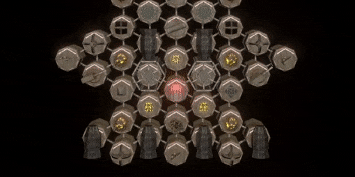
Animation below shows how the glow increases as the energy consumption goes up, evenly with all the modules. On overflow, modules get especially bright which means that the player should react. A consequence of ignoring the warning is shown at the end. Also notice the red glow of the cockpit (until it gets broken).
Prefabs and factories
All module types share the contents of previously created module base, so it would be useless to compose them over and over again with every new module type. Nested prefabs are a relatively new feature that suits my needs. By inheriting all module prefabs from the base module prefab, the common stuff gets included to all modules, and modifications to base module will be automatically applied to all its variants.
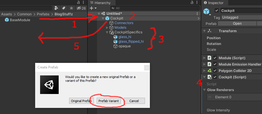
New prefab variants are done with the following steps.
- Drag the base module prefab from project view into scene hierarchy.
- Rename the game object appropriately ("Cockpit" in this case).
- Module-specific child objects are added inside the prefab. I try to keep them separated for easier maintenance.
- Module's functionality is implemented in a separate script and added into the new prefab's root (script is also named "Cockpit"). Adding scripts to base prefab's objects shouldn't be an issue.
- New prefab variant is created by dragging the modified object back to the project view and selecting "Prefab Variant" in the "Create Prefab" -dialog. The new prefab is now inherited from the original. Unity adds "Variant" suffix to the name, which can be removed.
A word of warning: albeit being a useful feature, nested prefabs are also an extremely easy way to ruin dozens of prefabs at once. Keep everything in version control and when committing, make double-sure that there are changes only in the prefab variants where there should be. I accidentally applied variant's changes to the parent prefab ("Apply All to Base" from the "Overrides"-dropdown), which messed up all the other module types. It took me a while to notice what I had done, but luckily I was able to revert.
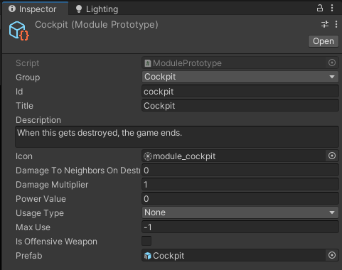
Now we need a way to associate prefabs to their corresponding module types and instantiate them. I'm using scriptable objects as factory assets (called prototypes in the game's context). They contain information that is common to all modules of its type: identifier, name, description, icon and all kinds of informational stuff. Additionally, prototypes have reference to the prefab variant they must make copies of. Below is the cockpit module's prototype/factory. Every module type has a similar one.
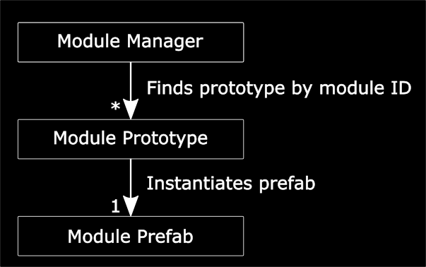
The last thing is to make a singleton manager object that contains a list of all prototypes. When given the module ID, it resolves the prototype object that in turn creates the module instance. Each created instance will be given access to its prototype. In ATP, ships are stored in simple JSON-files that tell what kind of module should be built at which position.
Problems/future enhancements
- At some point I’ll add a pilot to the cockpit. Perhaps ejecting from the cockpit towards the camera when the ship is destroyed… After all, we don't want anyone to get hurt in the fight.
- I’m not sure about the design of the reactor. Some kind of atomic 50’s sci-fi equipment could be better. But this will do for now.
- It's "translucent", not "transcluent". I never seem to get that right.
As always, thank you for reading, feedback is welcome. The next chapter deals with rotating, animated and otherwise non-static models. Before that, I hopefully get the 0.5.0 released.