Electronics And Mechanisms
Automatic doors? Combination locks? Timed explosions? These are all achievable using electronics and mechanisms!
This Dev Diary goes through the mechanisms in the game, and the electronic circuit blocks that can be used to control them.
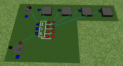
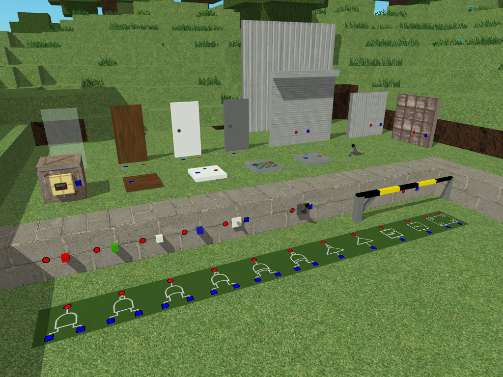 Above: An assortment of doors, switches, integrated circuits and other mechanisms.
 Note: The input/outputs (red circles/blue squares) and cables connecting them are invisible
The Voxel Turf electronic system allows you to link some blocks to each other with cables. For instance you can connect a door to a lever to control it. For all mechanisms the blue square is the input and the red circle is the output. Simply use a cable to link one input to one output to connect them!
So how does it work? To begin, electronic devices can have two states: Low (or Off), or High (or On).
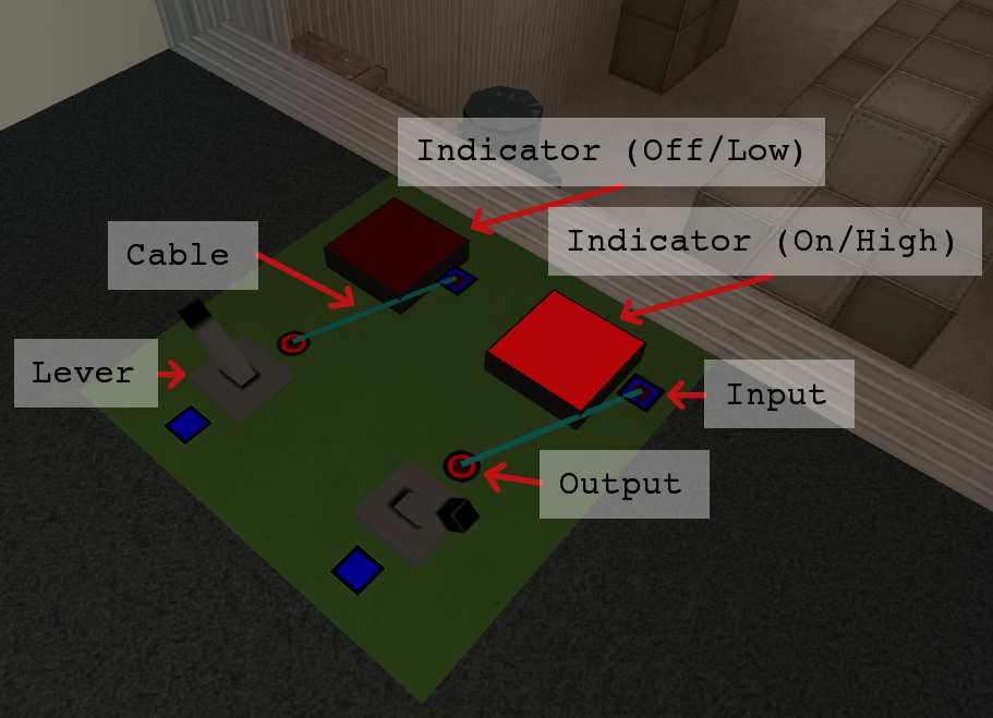
If you wish to connect one output to multiple inputs you'll have to use Splitters. Finally, to hide the clutter cables and ports are only visible if you have a mechanism or cable selected.
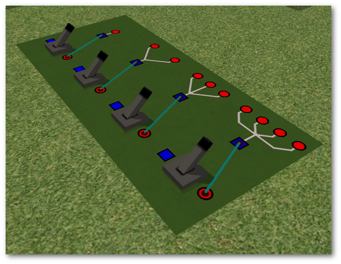
Splitters are used to send a signal multiple places
Applications
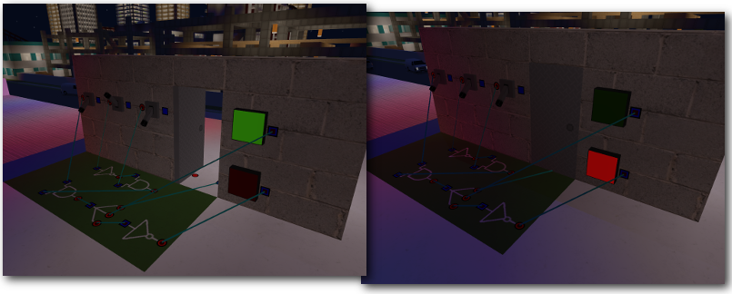
A 3-Lever Combination Lock, with indicators showing the state of the lock.
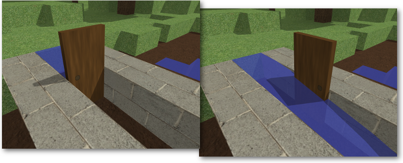
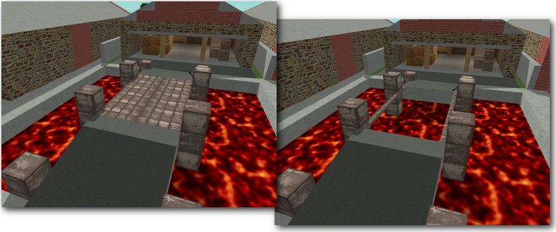
Liquids can pass through open doors, can be useful to create acid or lava traps!
Big retractable doors can be used to make drawbridges!
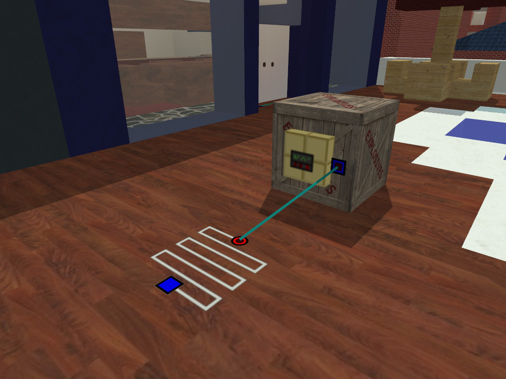
Explosive Crates can be hooked up to a detonator and a pressure sensor to create powerful land mines!
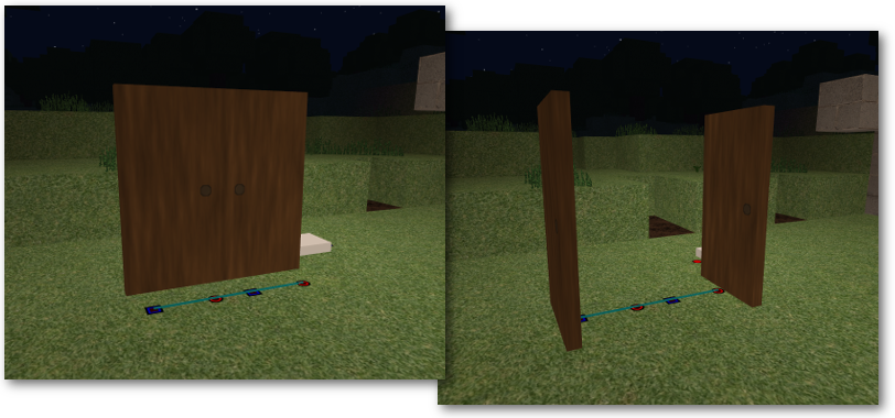
Doors can be wired to each other to make them open and close as a group
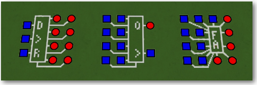
Integrated Circuits
In this section we'll find out how the integrated circuit blocks work.
Basic Utility
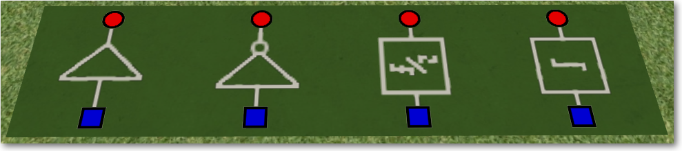 From Left To Right: Delay Buffer, Not Gate, Frequency Halver, Edge Detector
DELAY BUFFER – Delays a signal by 1 tick (half a second).
NOT – Inverts a signal – On becomes off and off becomes on.
FREQUENCY HALVER – Flips state every second pulse. Use this to convert buttons into switches.
EDGE DETECTOR – Acts like a Frequency Doubler, it flips state every edge (every transition from high to low or low to high). Use this to make a switch behave like a button.
Logic Gates
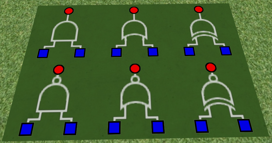
Top Row: AND, OR, XOR, Bottom RowNAND, NOR, NXOR
AND – Output is high if both inputs are high.
OR – Output is high it at least 1 input is high.
XOR – Output is high if 1 input is high and one input is low. This is good for implementing a light controlled by two switches.
Logic gates also come in inverted states:
NAND – Works like an AND gate with inverted output. Output is low if both inputs are high, high otherwise.
NOR – Output is low if either input is high.
XOR – Output is high if either both inputs are high or both inputs are low.
Latch
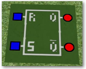
RS Latch – Has two inputs (S = Set and R = Reset) and two outputs (Q and NOT Q). If S receives a high pulse then Q is set to high. and remains high until R is pulsed. This is useful for setting and reading a state of something. For example you have an area with an entrance and an exit, and you want to know if a player is in the area. You can have a pressure sensor at the entrance wired to S, and sensor at the exit wired to R. If Q is high then the player is in the area.
Clocked Integrated Circuits
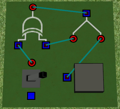
Above: An example of a clock pulse generator. An XOR gate has its output feeded back into it,
These are more complex, but extremely powerful integrated circuits.
JK Flip Flop - Works like an RS latch (J=S and R=K), but only updates when a pulse is sent to the clock input (>). If both J and K are high when a pulse is received, the output is toggled.
Counter:
Reading the lower 4 bits of the counter in No Clock mode
This is a 8 bit binary counter. You can use this for timing or counting things. It has two modes of operation:
1. No Clock (Timer Mode)
Do not connect anything to the clock input for this mode. This has 2 remaining inputs: I = Integrate, R = Reset. If I is high then the output increment once per tick (once ever half second). If R is high then the output resets to zero.
2. Clock Wired (Counter Mode)
When a pulse is detected on the clock input the device updates. If I is high then the count increments. If R is high the count resets.
Above: SIPO and PISO Shift Registers, and the 4-Bit Full Adder
SIPO Shift Register - SIPO means Serial Input, Parallel Output. When a clock pulse is received the state of D is written to output 1, the state of output 1 is written to output 2, 2 to 3, etc, and the state of output 8 is discarded. If R is high, the output is reset to zero.
You can use this to store numbers, such as the number of times a player has walked over a pressure sensor
PISO Shift Register - PISO means Parallel Input, Serial Output. The state of D is initially set to be whatever input 1 is. When a clock pulse is received D changes to input 2. Another clock pulse will set it to input 3, etc. After input 8 it jumps back to input 1.
4 Bit Full Adder With Carry - For a description on how a full adder works check out the wikipedia page. In a nutshell this is used to add two 4-bit binary numbers. To extend this to 8 bits, 12 bits, etc, you can tie the carry out and carry in bits between Full Adders.
That's it for this week! For updates, please Watch Us on IndieDb, or follow us on Steam or Facebook!


i liked it and also i noticed the tall buildings has elevators in but they dont work yet
Can't wait for the release keep up the good work ! :)
Any progress so far?