The woodwork part is done, now the electronics, with a bit of woodwork...First thing, I would like to show the trackball assembly, with a led attached below the trackball.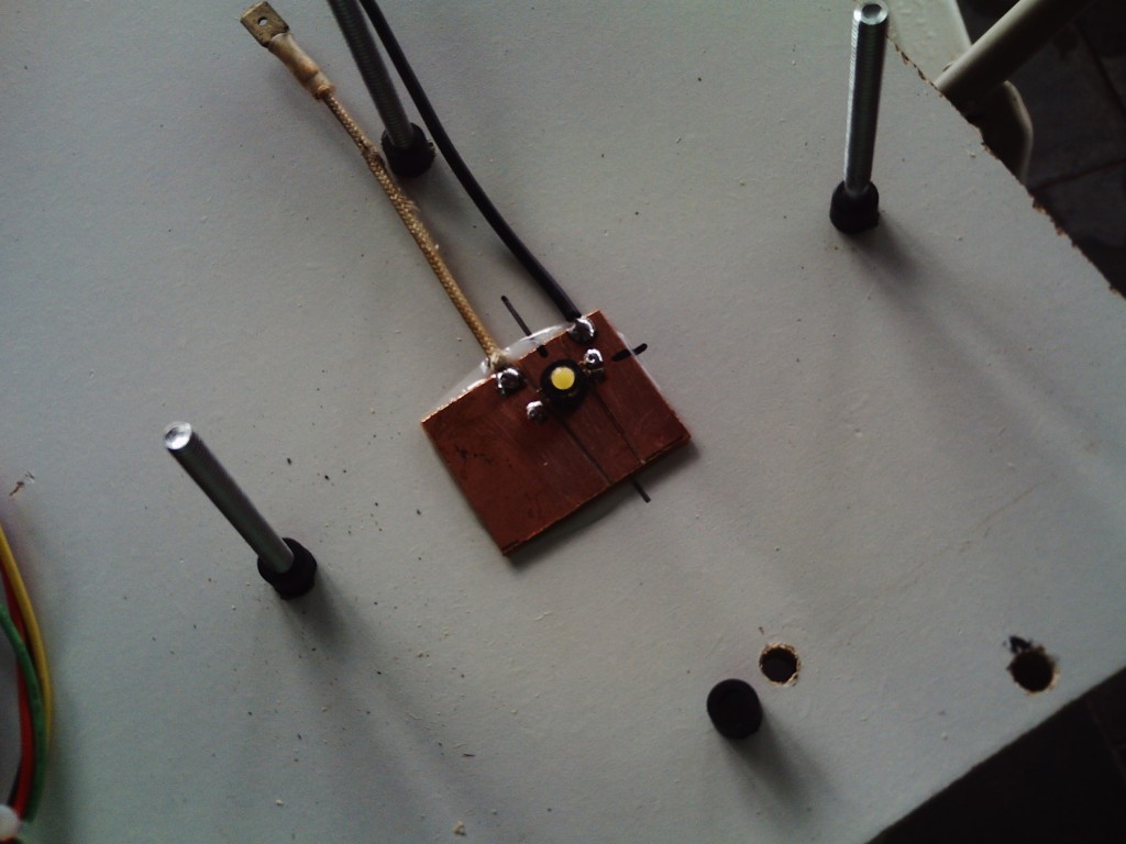 But since the LEDs are not done yet (as of the writing of this post), I will not talk more about them now, except for their assembly.Now, this picture show a not assembled button, and a assembled internals of one.
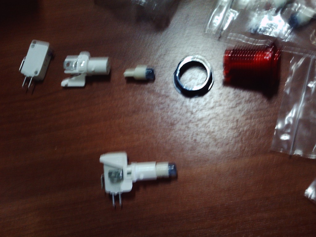 So we have, from left to right: the microswitch (this is the actual button), a assembly thing, a special led that fits inside the button and inside the assembly quite nicely, a nut, and a plastic button. It cannot be seen in the photo, but the plastic button has inside it a spring, and when you press it, two white prongs protude, these white prongs hit the red part on the microswitch (kinda hard to see on the photo, sorry...).The microswitch is the important part here, it has 3 prongs, one is the "ground" (black wire in the next photo), another is "normally open" (the other one with a wire attached) and another is "normally closed" (not used here). It detects when the button is in the opposite position than the position you put the wire. Thus, with the wire in "normally open", the switch will "trigger" when it closes (useful for buttons for example). If you put the wire on "normally closed" the switch "trigger" when it opens. (useful to detect that someone has opened a door, or removed a part for example).
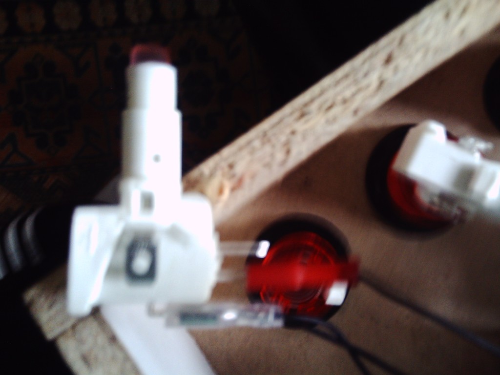 I inserted the buttons on the panel (from the "top" of the panel), then the plastic bolt from the below.
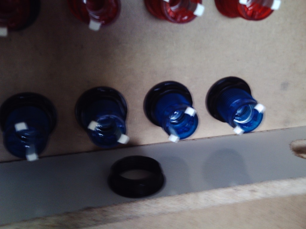 Then I plugged the white assembled stuff from the first photo inside the buttons.
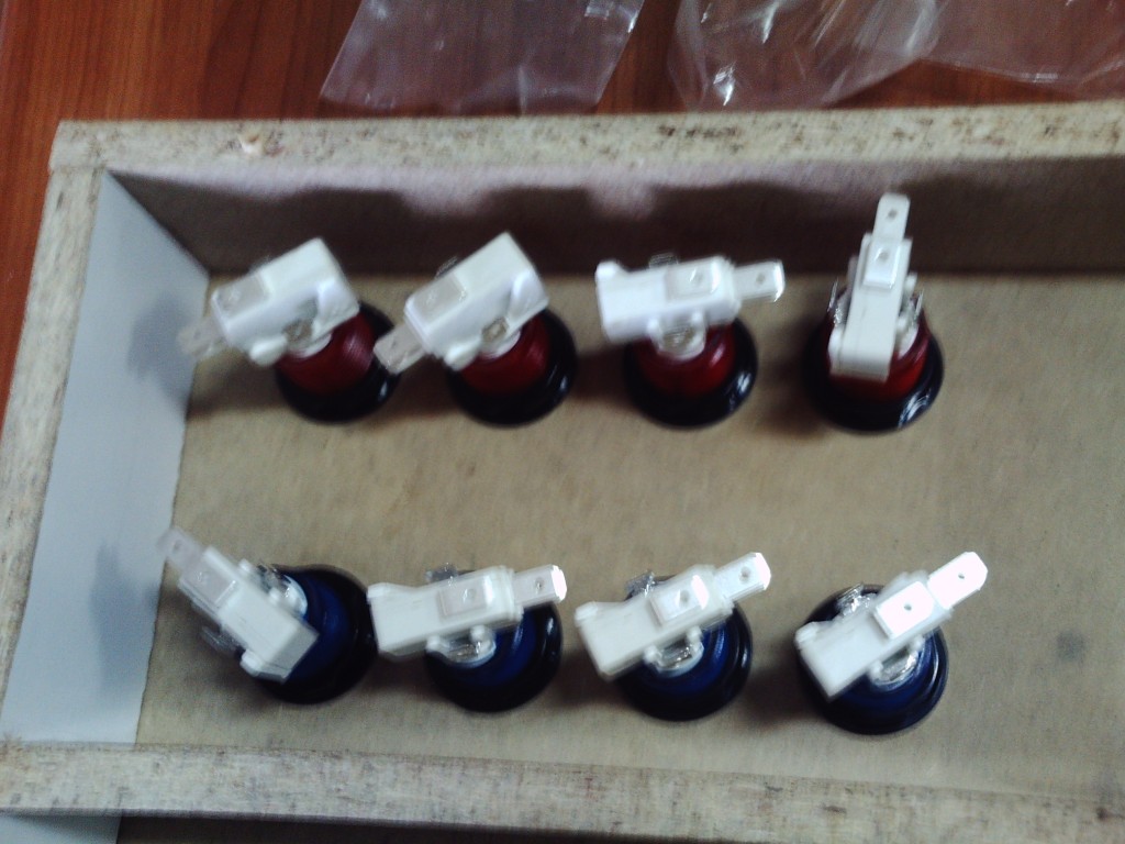 Then the wires, basically I had all wires organized into a harness, that harness was plugged into the control board with a standard IDE hard disc connector, each wire means one button, and thus I attached some wires to the previously mentioned "Normally Open" contacts of the buttons, the ground wire can be shared by all buttons, thus I had a really long wire with several connectors on it in regular intervals, I then attached that long wire in all buttons.
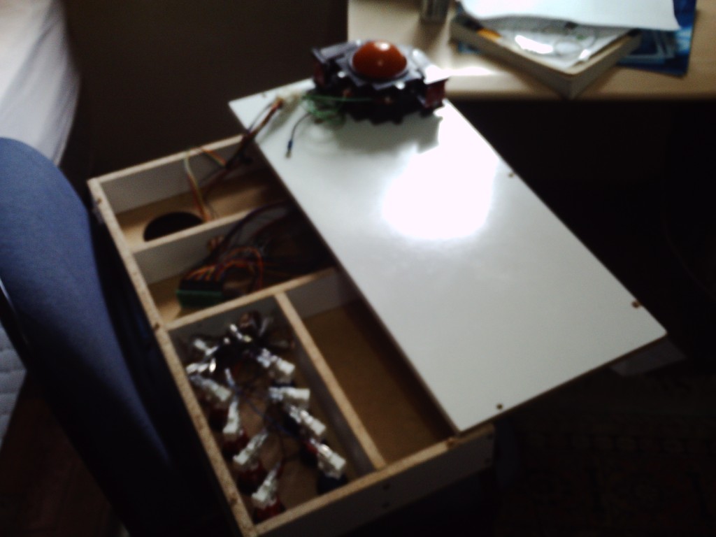 And that is mostly it :DThat is how the entire thing looks now:
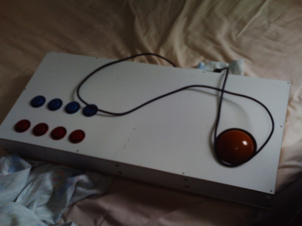 Now the lacking thing is the lightning electronics, all LEDs are in place, but they need yet proper electronics.The trackball needs 5 volts, that is provided from the computer USB port (I actually made a mistake with the trackball wires and the USB wire nearly melted... happily I found out what it was and fixed it).
Here is the first part on how I've made the electronics of the arcade controller.
Posted by Original_Speeder on


