![]()
This tutorial is part of a series of tutorials that will portrait every step from the creation to the implementation of the FAB-500-M62 bomb in the game.
In the previous tutorial we done the all the modeling, now it is time to move to the mapping
As mentioned in the first part, this tutorial will explain in detail the whole process to help even the most inexperienced modelers.
![]()

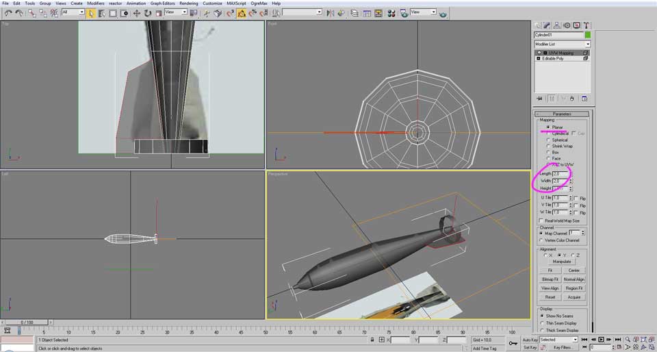
After the modeling is completed, select the bomb model and in the “Modifier List” choose “UVW Map”
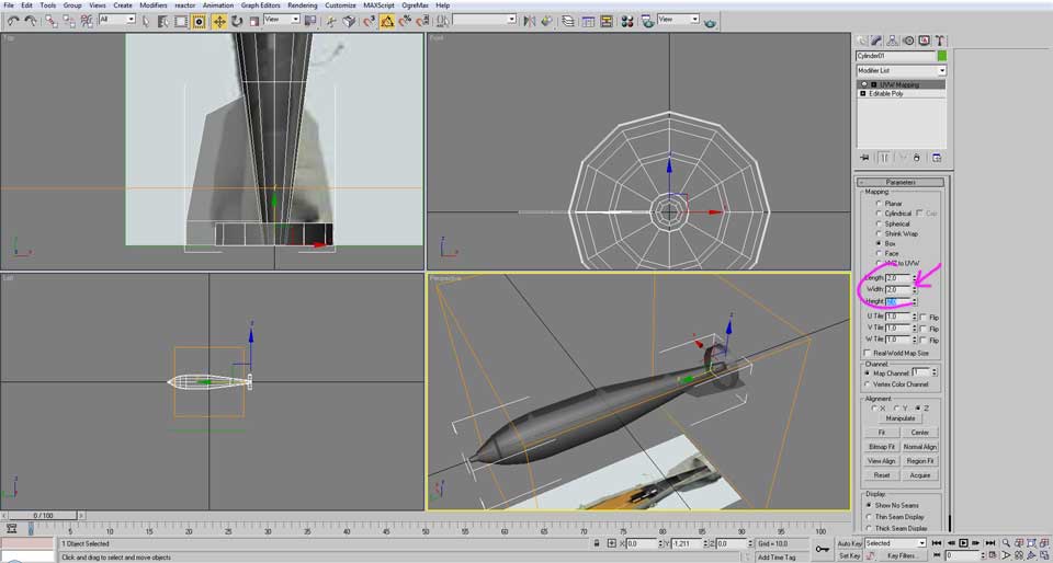
Then, select The “Box” and write the same value in the 3 fields bellow, the value have to roughly encapsulate the entire model.
The reason of this value being the same in the three fields is to avoid having mapping distortion latter on.
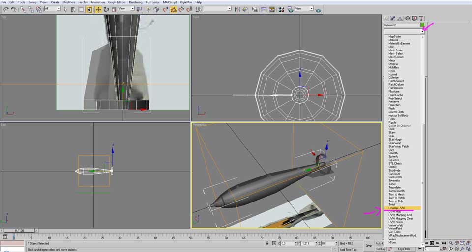
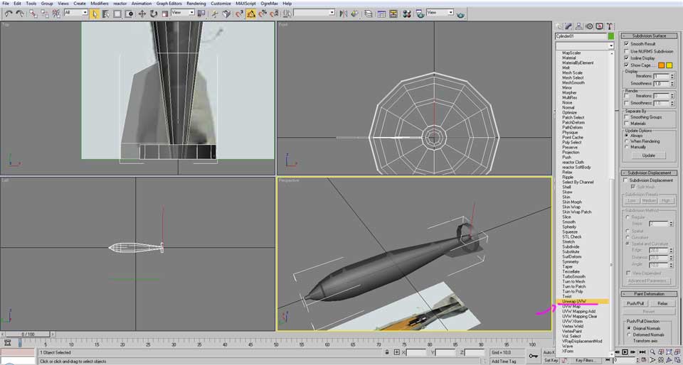
After configuration the “UVW Map” go to the “Modifier List” chose the “Unwrap UVW”.
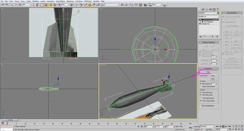
Then click in the “Edit” button.
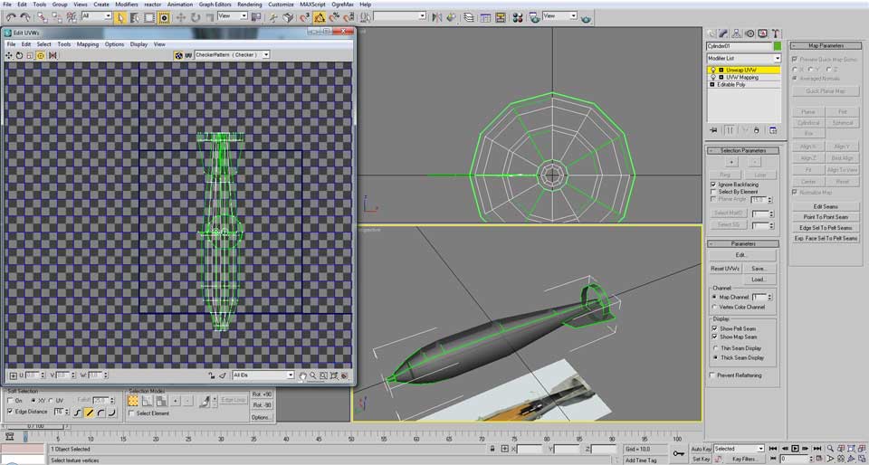
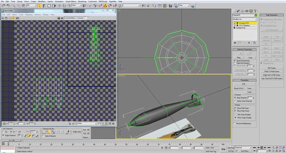
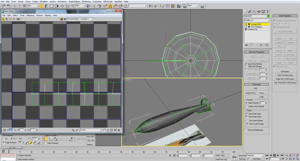
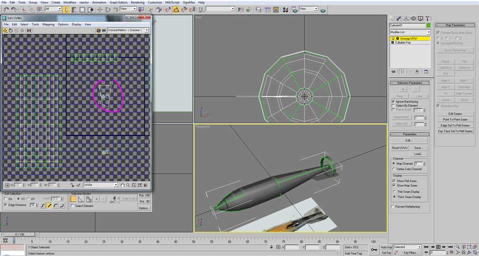
After clicking in “edit” it automatically opens a new window. This is the “edit UVWs” window and it will be used organize the model’s UV mapping.
As you can see, at this moment there is a group of lines clustered in a way that resembles the model. Our next step is to organize all these surfaces in a clean and easy way place the bomb texture in them..
First, let’s break this cluster of lines in order to be able to see what surface they represent.
One of the ways is to move them as faces. To choose that control, click in the right mouse button and select “Face”.
Then select some surfaces. (The selection was made in the “Edit UVWs” window, but the same selection can also be done in the Viewports)

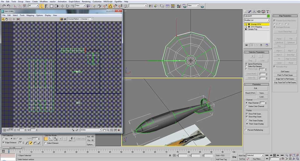
After selecting a group of faces, click again in the right mouse button and then clink in “break”, this breaks the connection of the selected faces with others , this way we can move the surface without dragging and distorting other faces.
Then move the selected group of faces to an empty space.
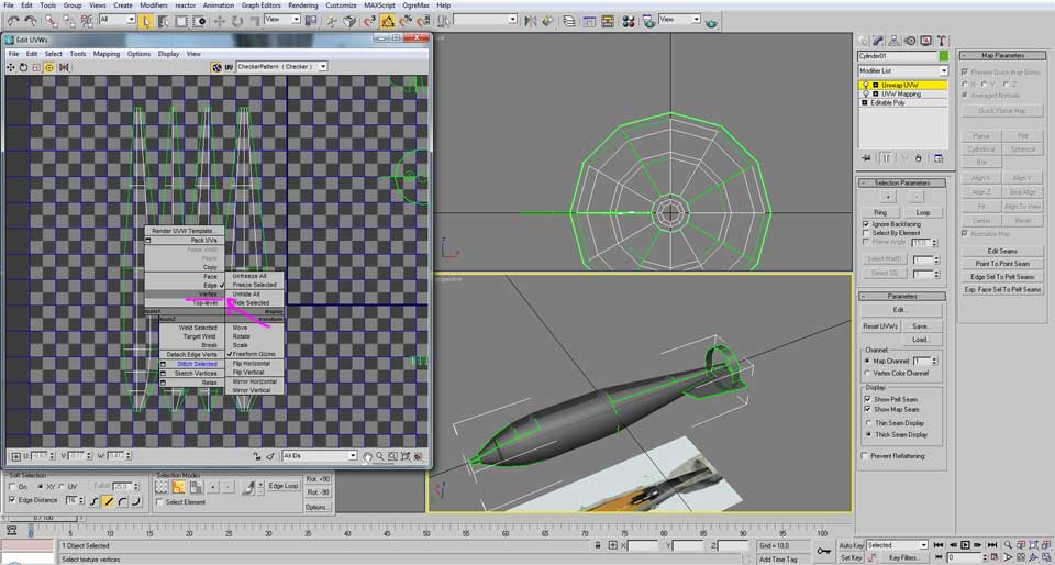
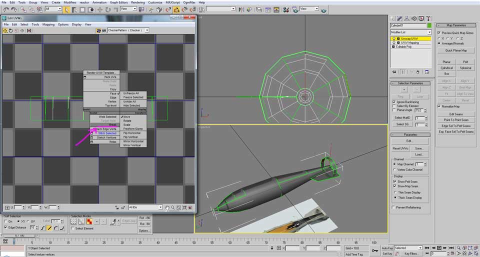
After moving, click again in the right mouse button and chose the “Edge” control.

Now, it is time to start organizing this part of the model.
As the body of the bomb is a cylindrical shape, what we want to do, is to select a lateral face and start unwrapping along the surface.
For that select one of the vertical edges in the borders. (By default, the green lines mean they have a broken connection)

After selecting that edge, click again in the right button and select “Stitch selected”.

As you noticed some faces moved and become attached to that edge.
Continue doing the same until the last edge of the strip is the one that connect to the starting edge.
(you will notice this when the starting edge turn blue after selecting the last edge)

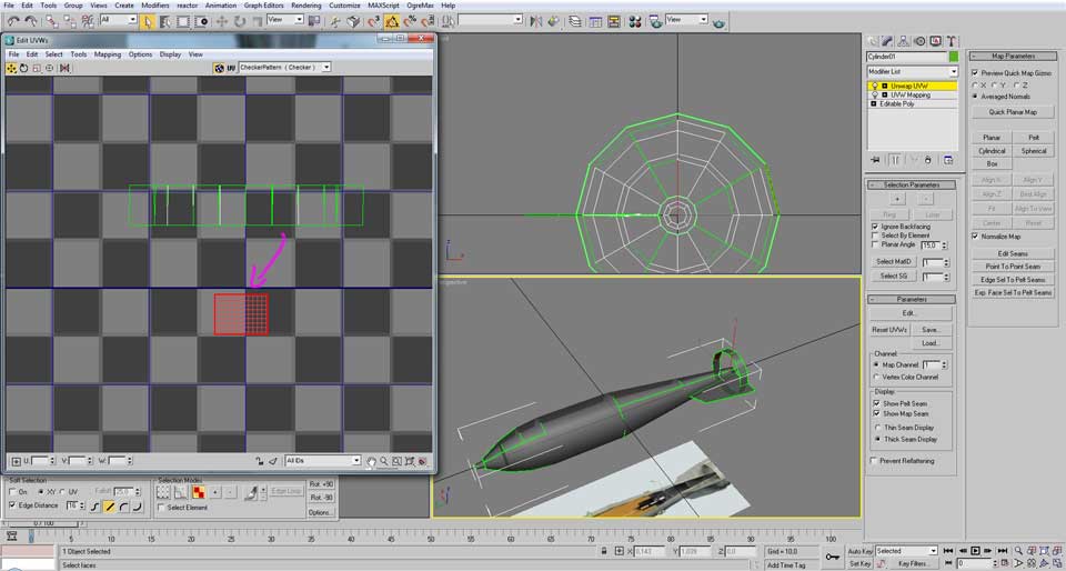
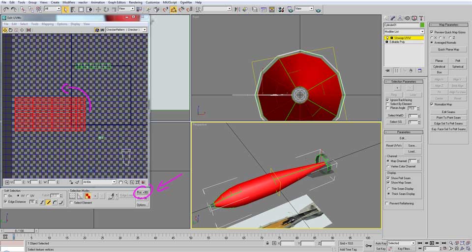
Now, select some of the horizontal edges above and “stitch selected” to attach the faces that belong to the tail of the bomb.
Let’s ignore the body of the bomb for just a moment, now, move out of the way the tip of the bomb that came along when we moved that initial group of faces to an empty space.
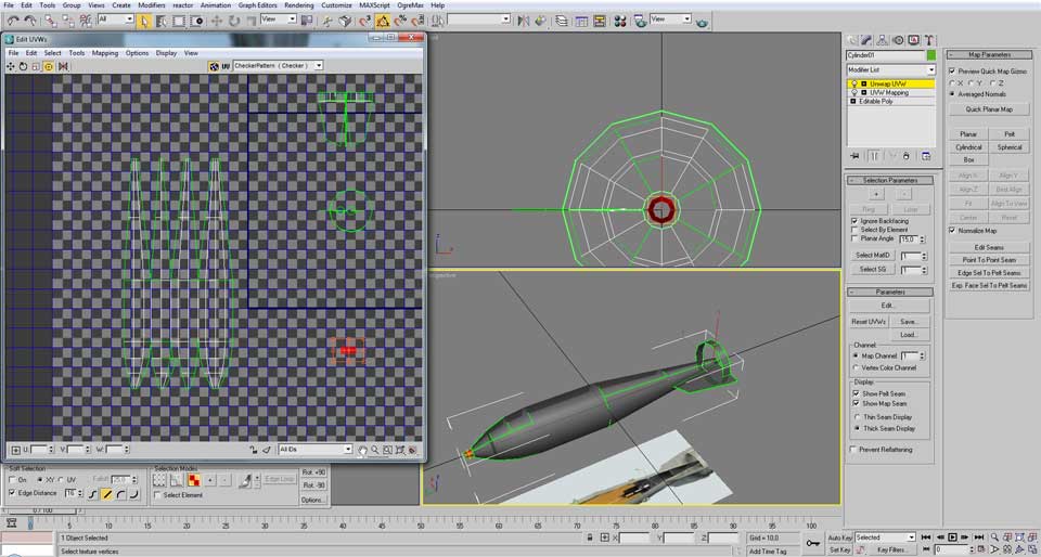
Now onto the body again, let’s select “vertices” control after clicking the right mouse button.

Now select one of the vertices of the perfectly vertical edge.

Copy the value of the first field (while it says U, it represents the usual X position)
Select all vertices of that border, including the one we copied the value.
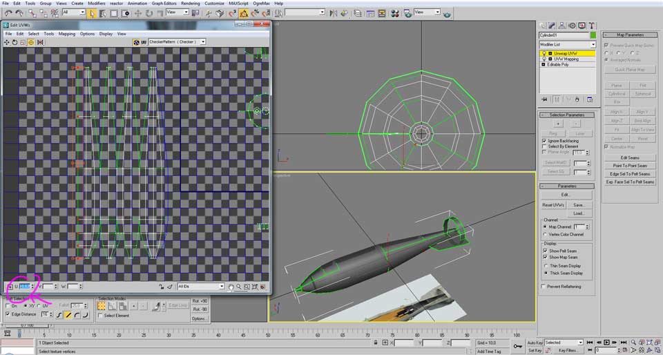
Then paste the value in the same field, as you may noticed that line has become completely strait.
Do the same to all other vertical array of vertices.

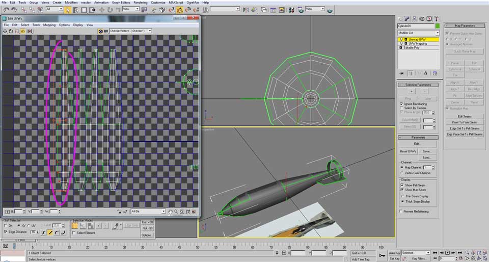
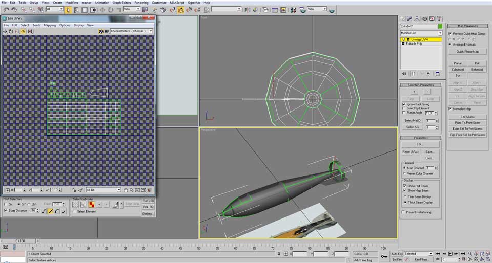
Now let’s focus again in the fuse of the bomb that we moved to other place before.
The first make all lines completely vertical by the method of copy paste the U position, then “stitch selected” all green lines unit the last lines can only be stitched together.

Let’s move out of the way the planar fin, for now we don’t want to do anything with it.
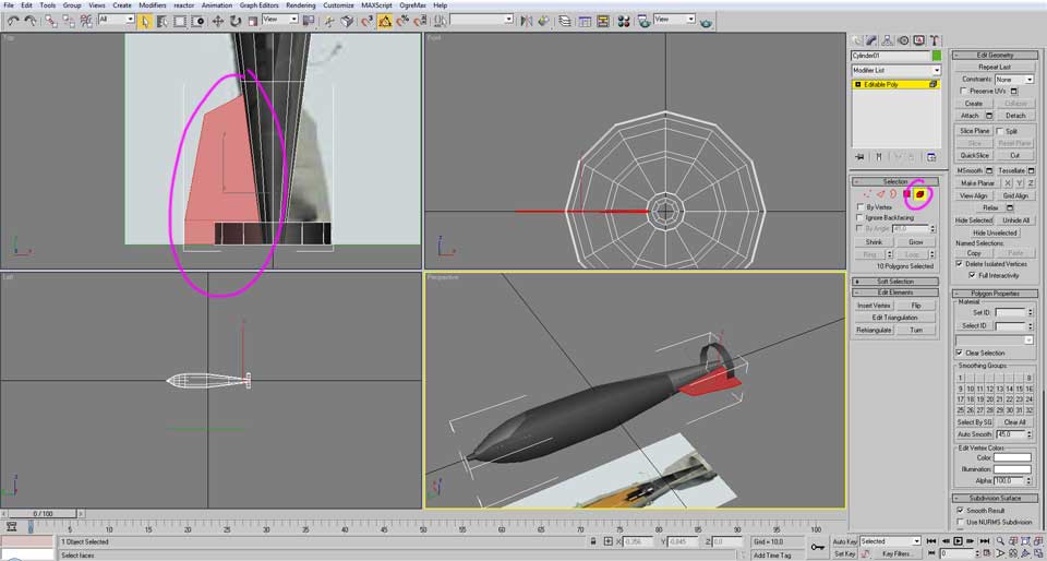
Select one of the faces.
In this image, you can see that some faces are on top of each other, it is best that we organize it in a way that we can perceive what we are doing.
To do that, click in the right mouse button and chose “Brake” while keeping that face selected
Move that face to an empty position

Perform the “Stitch selected” routine as usual
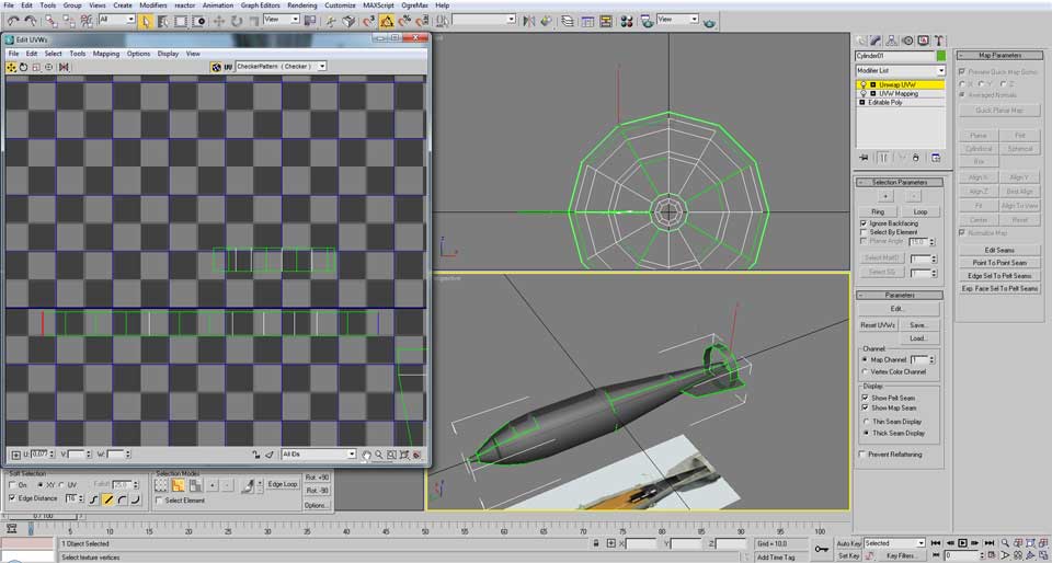
Now we have a complete strip (as you can see the end in red can only be connected to the end in blue, so we don’t what to do that or those faces will become distorted.)
Now, there are some faces left in that cluster, they belong to the other side if the cylindrical fin. To arrange them with the others, select the top horizontal edge from the organized strip and make “stitch selected”.

Continue with the “stitch selected” until all the faces are positioned.
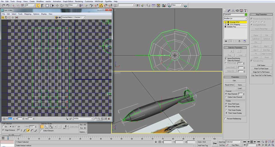
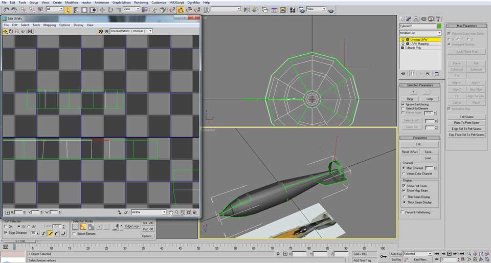
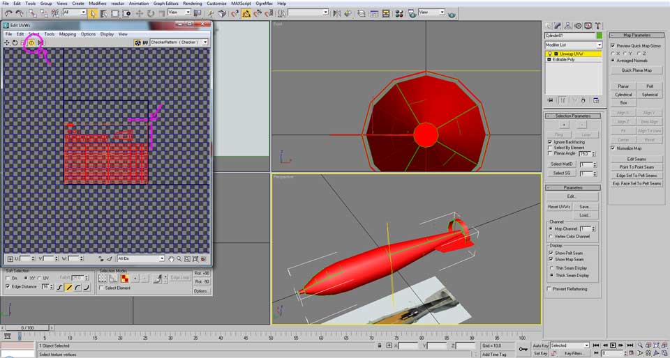
Now it is time to make those vertical lines perfectly strait, use the usual copy/paste of the U values.
With that done, the UV mapping is almost complete. (notice that we didn’t do anything to the planar fin.)
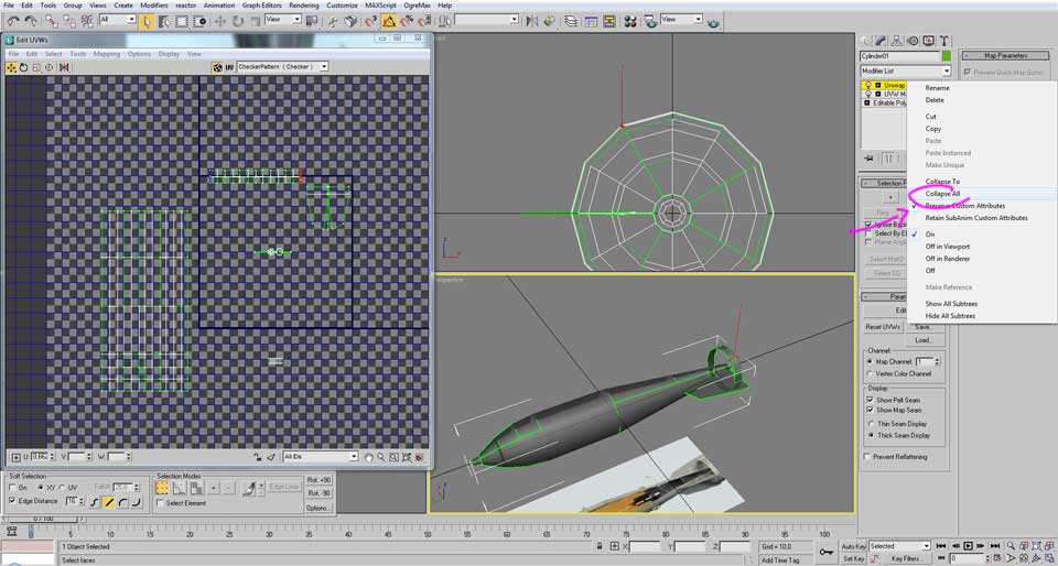
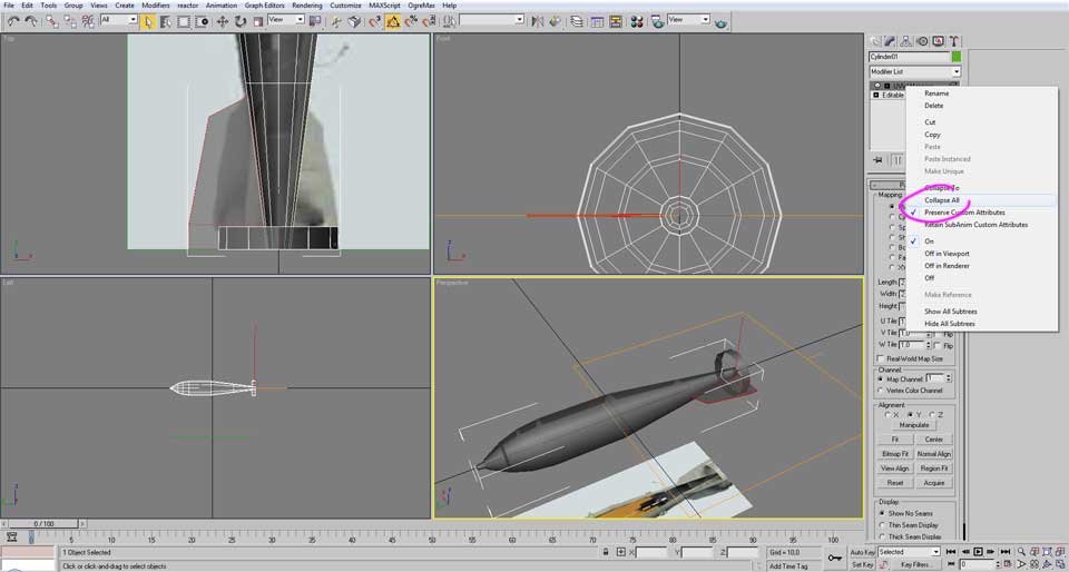
To complete the process, right click in the “Unwrap UVW” just below the “Modifier List” and chose “Collapse all”
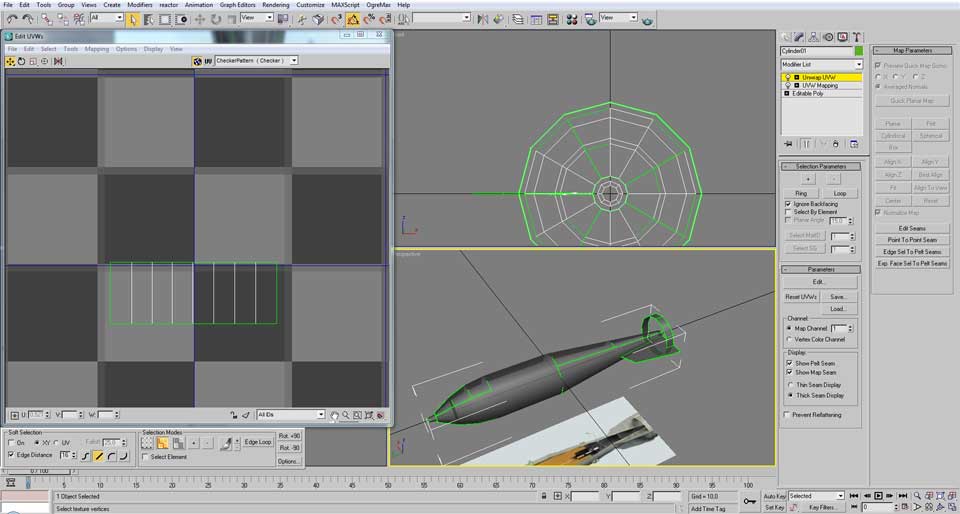
Now select the “Element” selection control and click in the planar fin.
Then select the “UVW Mapping” in the “Modifier list” but this time keep the mapping to “Planar” and set the same values as before.
Then use “collapse all” in the “UVW Mapping”
After the collapse chose “Unwrap UVW”.
The planar fin is placed in the center, notice how it only has white lines, that is because it doesn’t have any broken face, we will keep that way for this weapon because it will have the same texture detail in both faces
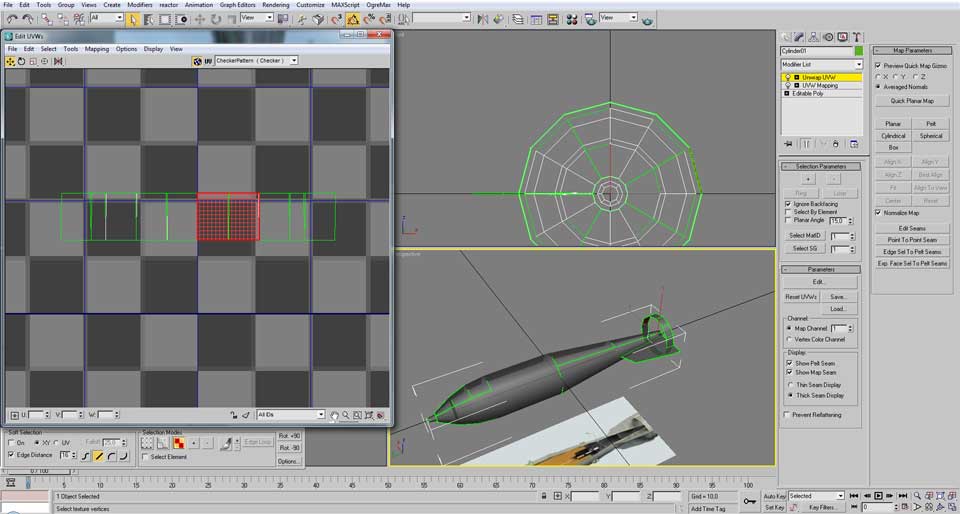
And finally, the last step of the UV mapping is to fit everything in that blue lined square.
For that, let’s start by rotating counter clockwise the body of the bomb and move it to inside of the square.
After moving and rotating all the surfaces, they are now packed as tightly as possible, however they still go beyond the blue borders of the square.
In order to fit, we have to scale down, that scaling can be done by selecting the “Freeform Mode”, then left mouse click and hold in the upper right point of the freeform square and while holding also press the keyboard “ctrl” key and then move the mouse to shirk the size until it fits inside.
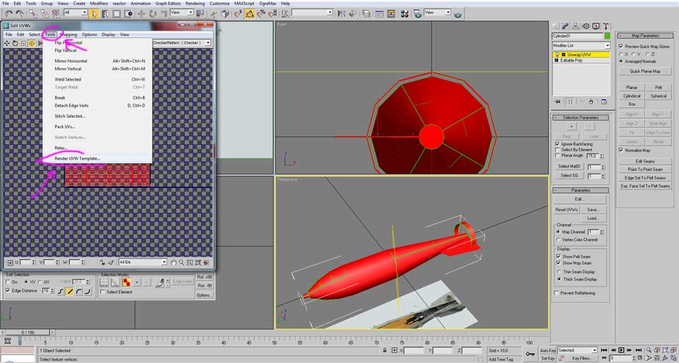
With that done, we have the UV mapping complete, the only action that needs to be done more is saving that mapping to an image file so it could be used in the texture creation.
To do that, open the “Tools” and then click on “Render UVW Template”.
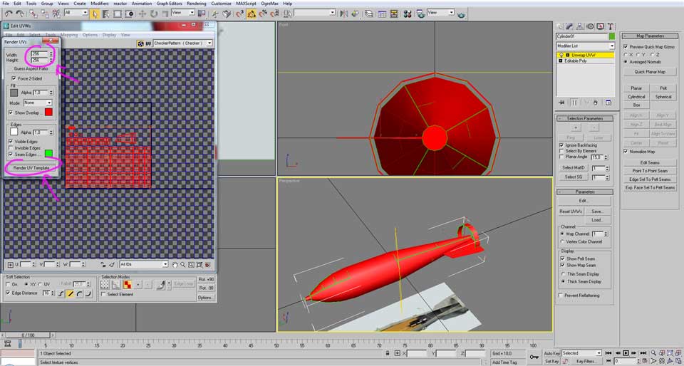
A new window appears, for a bomb weapon an image size of 245x256 pixies is more than enough. Then click in the “Render UVW Template” button.

A new window appears with the desired texture. Save it on your desired folder but as a “png” file.
![]()
As Uv mapping is done, the next step is the light mapping.
The light mapping is a step that saves how the model is illuminated in a specific lighting condition
This step is purely optional, but with just a few clicks it can help making the textures a lot more interesting, so it is highly recommended.
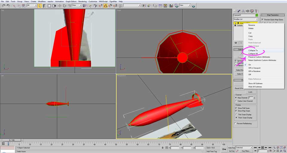
If you still have the “Unwarp UVW” active there click in it and then “Collapse All”

Then select the planar fin and click in “Detach” button.
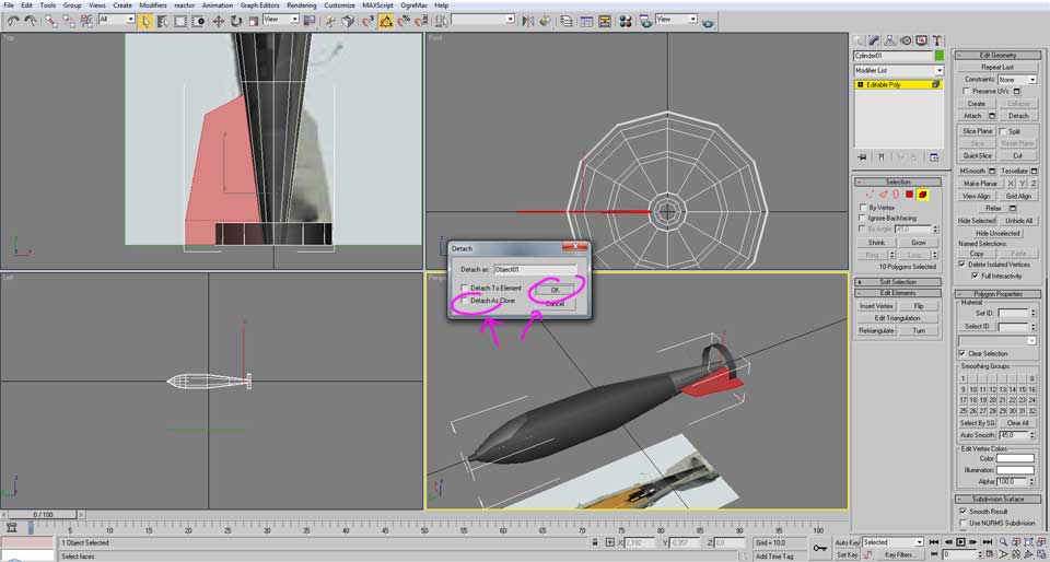
Be sure it doesn’t be detached as a clone and then click in ok.

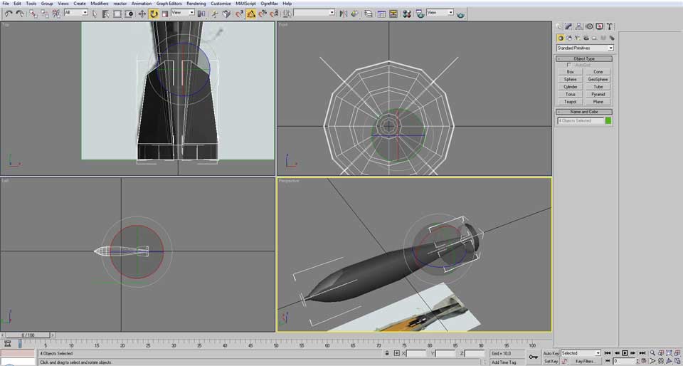
Now rotate 45 degrees to the desirable position. In that place, hold the “shift” keyboard and rotate again, but this time 90 degrees.
After releasing the mouse key it will open a new window about the clone creation, create it as a “Copy”.
Repeat the process two more times to have in total four planar fins.

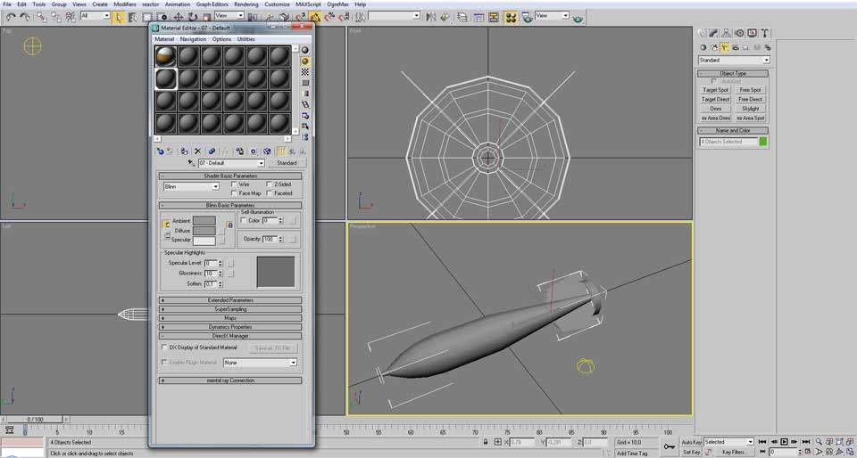
Then select the bomb again and click in “attach” button and apply to just one planar fin.
With that done, go back to the “Create” tab and select all bomb related objects (do not select the plane with the reference image)

Click in the right mouse button and chose “Hide Unselected”.

In the “Create” tab, chose the “Lights” button below and plane a “Skylight” in the perspective viewport.

Now select the bomb model again.
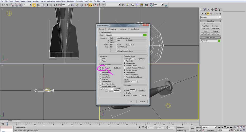
Right click and go to the “Object Properties” and disable the “See-through” option
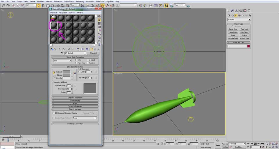
Then open the material editor by pressing “M” and chose and unused material
Apply that material to the bomb.
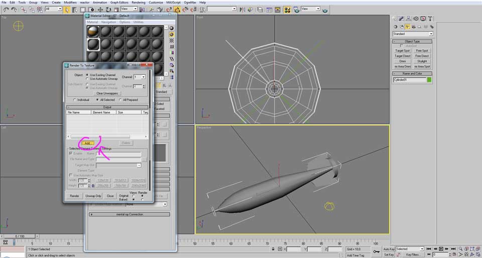
Now with just the bomb model selected (with only one planar fin attached) open the render to texture window by pressing the “0” key.
Then click in the “Add” button.
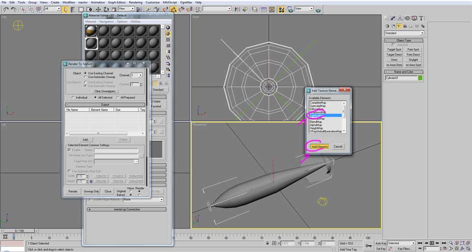
In the new window that opens choose “LightingMap” and then click in “Add Elements”
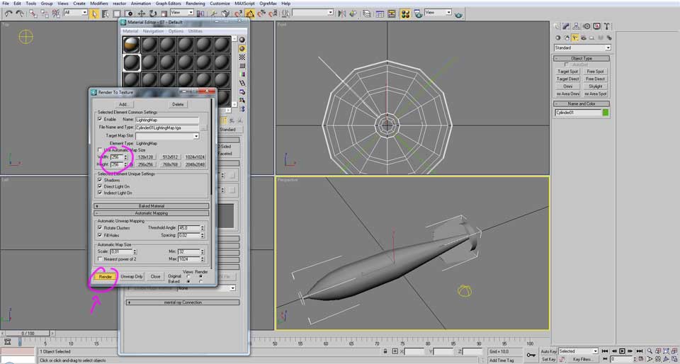
Set the same image size as the “Render UVW Template” (that was 256x256 pixies) and then click in “Render”
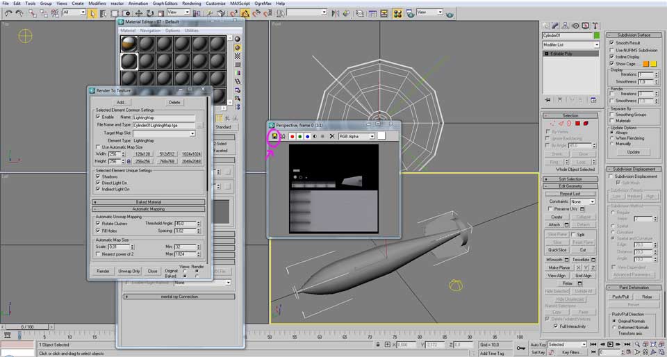
The PC will start rendering the image (and may take a while). After it is done, it will appear in a new image, save that image in the desired folder as a “png”
And this concludes the UV mapping and light mapping; the next part will be showing the texture creation.


As someone else has previously stated before;
TS, we can't wait until you make plane creation tutorials!
I know and it will be up soon, but I decided to start with a simple model as this bomb to introduce everyone that is not used to the modeling with a very detailed step by step tutorial.
The aircraft tutorial will be detailed as well, but not at this level, or else it would require nearly 20 parts just for modeling the aircraft.