Hello everyone! Today is another blog post, and it's one of my favourite topics: Rendering Terrain.
Now, just to be clear. I'm not the best source in the world on this subject. However, I do know the who the best source is, and I will happily link it:
Iquilezles.org
Inigo Quilez is the best resource I've found for rendering gorgeous landscapes. If somehow you didn't spend 10+ hours drooling at his work both on his website and then on Shadertoy, let me show you how we're doing it.
For this process, we're gonna use a fairly useful OpenGL feature: Tesselation Shaders.
These guys are basically an extension to a vertex shader: In a regular OpenGL application, the vertex shader (VS) takes in your model data (in our instance, the planet surface), and then feeds it to a fragment shader, which fills out the pixels that fall into the triangles in the vertices. Now, I won't go into too much detail about how the shader pipeline works, but the gist of it is that tessellation shaders (TS) come after the VS. The TS takes in primitive info from the VS, and then adds more primitives based on some mathematical function you describe as the developer.
Confused yet?
Oh, and TS come in two flavors: Control, and Evaluation. Control TS specify how many new primitives are emitted, and the evaluation TS specify how they are processed.
While I'm not making this sound simple, looking at the code is going to make a lot of sense, I swear. But first, a before picture:
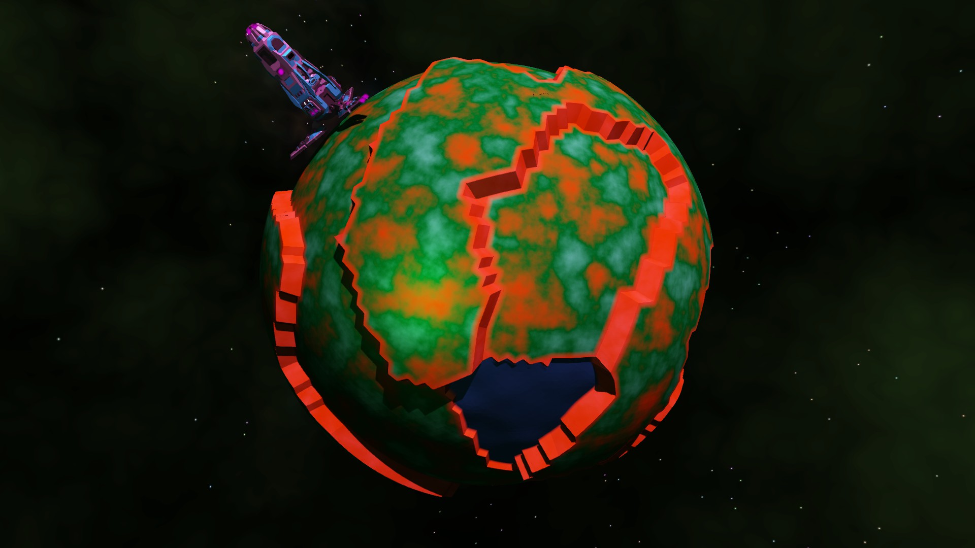
Our planet looks okay (certainly as good as the ones on the screenshots over on at Store.steampowered.com, shameless plug). However, adding in a bit of physicality is going to vastly improve it.
First, let's take a look at the control shader:
#version 430 core
layout(vertices = 3) out;

layout (location = 0) in vec2 vTexCoords[];
layout (location = 1) in vec4 vPosition[];
layout (location = 2) in vec2 vNoiseCoords[];
layout (location = 3) in vec3 vNormal[];
layout (location = 4) in vec3 vWorldPos[];

layout (location = 0) out vec2  tessTexCoords[];
layout (location = 1) out vec4  tessPosition[];
layout (location = 2) out vec2  tessNoiseCoords[];
layout (location = 3) out vec3  tessNormal[];

uniform int modelID;
uniform int currentPlanet;
uniform int nullplanet;
uniform int lodState;
uniform vec3 cameraPosition;

void main(void)
{
    float distanceFromCamera = length(cameraPosition - vWorldPos[gl_InvocationID]);

    float tessPowerInner = 1.0;
    float tessPowerOuter = 1.0;

    if(lodState == 1){
        float TessPower = 4.0 - (distanceFromCamera) / 500.0f;
        tessPowerInner = clamp(TessPower, 1.0, 3.0);
        tessPowerOuter = clamp(TessPower, 1.0, 3.0);
    }else{
        tessPowerInner = 3.0;
        tessPowerOuter = 3.0;
    }

    tessPosition[gl_InvocationID] = vPosition[gl_InvocationID];

    gl_TessLevelInner[0] = tessPowerInner;
    gl_TessLevelInner[1] = tessPowerInner;

    gl_TessLevelOuter[0] = tessPowerOuter;
    gl_TessLevelOuter[1] = tessPowerOuter;
    gl_TessLevelOuter[2] = tessPowerOuter;
    gl_TessLevelOuter[3] = tessPowerOuter;

    tessTexCoords[gl_InvocationID] = vTexCoords[gl_InvocationID];
    tessNoiseCoords[gl_InvocationID] = vNoiseCoords[gl_InvocationID];
    tessNormal[gl_InvocationID] = vNormal[gl_InvocationID];

}
This doesn't look quite like some of the other shaders I've put up so far, so let me explain. With a Control RS, you first have to specify how the shader spits out primitives. In our case, we want triangles, so we specify that with (vertices = 3).
Next, all the outs for the shader that's going to feed into the next shader stage need to be declared as these arrays: This notation will be similar if you've written geometry shaders before.
Then we begin the shader. It's not particularly compilcated, we just have to specify 2 built-in variables, and then feed in the bits of vertex data that we're going to need in the next stage.
The two built-in variables are tessPowerInner, and tessPowerOuter. What do these do? Well, in a word, they tell the hardware how we want the primitives to be chopped up: Note that this shader stage can take in more than just point primitives. In fact, this application takes in triangles, and then chops them up into smaller triangles. Now, how these power levels cut up the triangles is somewhat complicated, so I'm going to just link the OpenGL specs (Khronos.org ), and let you take a look there and see what makes sense for your application. This bit of code will look only slightly different if you're rendering with Quads, for example. I set the "chopping up amount" based on camera distance, so we get some Level-Of-Detail action going on. Because Zero Sum Future can have some objects drawn far away, it makes sense to not increase the primitive count on far-away objects that won't have that much detail anyway.
Next, we pass-through the primitive info we get from the VS. Again, because this stage takes in a triangle, and spits out triangles, we have to use glInvocationID to get the correct data.
Now, if you're sharp, you'll have noticed that something might be off. We took a triangle, told our shader to chop it up based off of camera distance, and then passed through the vertex data we got from our memory. In essence, we took 3 corners of a triangle, and then turned it into many more. Where are all these corners going to get the data they need to be drawn correctly, like position and normal?
Yeah, the control shader was the easy shader.
#version 430 core

layout(triangles, fractional_odd_spacing, ccw) in; layout (location = 0) in vec2  tessTexCoords[];

layout (location = 1) in vec4  tessPosition[];

layout (location = 2) in vec2  tessNoiseCoords[];

layout (location = 3) in vec3  tessNormal[];


layout (location = 0) out vec2  geoTexCoords;

layout (location = 1) out vec4  geoPosition;

layout (location = 2) out float  geoCrackDepth;

layout (location = 3) out float  geoResourceType;

// matrices for drawing shit


uniform int modelID;

uniform int planetType;


layout(binding = 0, rgba32f) uniform readonly restrict image2D inputTex;

layout (binding = 4) uniform sampler2D heightTexture;


float getNoise(ivec2 Coords){
	float noise = texelFetch(heightTexture, Coords, 0).r;
	return noise;
}

float hash(float n) { return fract(sin(n) * 1e4); }

float hash(vec2 p) { return fract(1e4 * sin(17.0 * p.x + p.y * 0.1) * (0.1 + abs(sin(p.y * 13.0 + p.x)))); }

float noise(vec3 x) {
	const vec3 step = vec3(110, 241, 171);
	vec3 i = floor(x);
	vec3 f = fract(x);
	// For performance, compute the base input to a 1D hash from the integer part of the argument and the
	// incremental change to the 1D based on the 3D -> 1D wrapping
    float n = dot(i, step);
	vec3 u = f * f * (3.0 - 2.0 * f);
	return mix(mix(mix( hash(n + dot(step, vec3(0, 0, 0))), hash(n + dot(step, vec3(1, 0, 0))), u.x), mix( hash(n + dot(step, vec3(0, 1, 0))), hash(n + dot(step, vec3(1, 1, 0))), u.x), u.y), mix(mix( hash(n + dot(step, vec3(0, 0, 1))), hash(n + dot(step, vec3(1, 0, 1))), u.x), mix( hash(n + dot(step, vec3(0, 1, 1))), hash(n + dot(step, vec3(1, 1, 1))), u.x), u.y), u.z);

}

#define NUM_OCTAVES 5

float fbm ( in vec3 _st) {

    float v = 0.0;
    float a = 0.5;
    vec3 shift = vec3(100.0);
    // Rotate to reduce axial bias
    mat2 rot = mat2(cos(0.5), sin(0.5), -sin(0.5), cos(0.50));
    for (int i = 0; i < NUM_OCTAVES; ++i) {
        v += a * noise(_st);
        _st = _st * 2.0 + shift;
        a *= 0.5;
    }
    return v;
}

void main(){

	int instanceNumber = 0;
	float frequency = 5.0f;

	vec2 texCoords = tessTexCoords[0] * gl_TessCoord.x + tessTexCoords[1] * gl_TessCoord.y + tessTexCoords[2] * gl_TessCoord.z;
	vec2 noiseCoords = tessNoiseCoords[0] * gl_TessCoord.x + tessNoiseCoords[1] * gl_TessCoord.y + tessNoiseCoords[2] * gl_TessCoord.z;

	vec3 normalAtLocation = normalize(tessNormal[0] * gl_TessCoord.x + tessNormal[1] * gl_TessCoord.y + tessNormal[2] * gl_TessCoord.z);


	geoTexCoords = texCoords;

	vec3 pos = tessPosition[0].xyz * gl_TessCoord.x + tessPosition[1].xyz * gl_TessCoord.y + tessPosition[2].xyz * gl_TessCoord.z;

	float radius = length(pos);
	float heightMulti = 2.0;
	float height = 0.0;
	vec4 worldPos;

	//convert the resourceEnum into -1 / 1:

	if(length(pos) < 101.0){
		geoResourceType = 0.0;
	}else{
		geoResourceType = (texture(heightTexture, noiseCoords).g * 2.0) - 1.0;
	}

	if(abs(geoResourceType) < 0.1){
		geoResourceType = 0.0;
	}

	float noiseVal = texture(heightTexture, noiseCoords).r;

	noiseVal -= 0.5;
	noiseVal *= 2.0;

	geoCrackDepth = 0.0;

	if(noiseVal > 0.0){
		heightMulti = 1.5;
	}else{
		heightMulti = 4.0;

		geoCrackDepth = abs(noiseVal);
	}

	height = noiseVal;

	pos = pos + normalAtLocation * (height * heightMulti - 1.0 - abs(geoResourceType) * 3.0); //basedrop + terrain height adjustment + resourceHeight adjustment

	worldPos = vec4(pos, 1.0);

	gl_Position = worldPos;
	geoPosition = worldPos;

}
Yeah, this is horrible. No fear though, I'm going to explain it, and it's pretty simple.
Before we do anything, we specify what kind of data we're taking in with the (triangles, fractional_odd_spacing, ccw) declaration. Why that specific declaration? Well, like I said, we're doing this in triangles entirely, and so we specify triangles. We also use fractional_odd_spacing, because, well, it looked the best. Well, that, and that mode can specify a 0 tessellation power without throwing errors.
Okay, next job is to construct the basic data of the primitives in question. Now, I have to be careful with my wording here: This shader stage takes in triangles (in our application), and then spits out individual vertices – each point having texture coordinates, world positions, and all the important bits of info we need to draw things correctly. So the very first job is to contruct some of this info using a scary math word: Barycentric coordinates.
Now, I'm a physics graduate, and I could not explain Barycentric coordinates to you even if I tried. At least, not well. Oh, and because this is only one example of tessellation shaders, these conversions will only work for triangle-specific applications. So I will again link the resource I used to figure it out (OpenGL wiki saves this blog again Khronos.org ), and leave it as an exercise to the reader.
For triangles, which is what most applications will use, you multiply each component in order with the in-build gl_TessCoord components in order. That gives you continuous interpolations of the triangle in question.
Next up, I do something quite silly. I obviously do not want to just leave the primitives as they are interpolated – that won't get me any texture... on my textures! So I need to introduce some noise. But not just any noise: If you randomly assign noise, it looks like this:
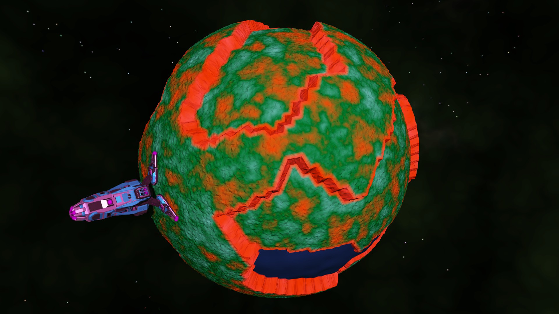
While that honestly doesn’t look too bad (much better then our before picture), the noise needs to make some sense. Let's assume that I'm clever enough to generate that noise texture on the fly (maybe a future blog, huh?). And let's say I'm clever enough to map that into a texture and get it into my shader as heightTexture. I still need to sample that somehow.
Now, there are many clever and intelligent ways to do this. There are many mappings from a 2D rectangle to the surface of a sphere. I... did not use any of those. I used a noise function I found on this very handy resource ( Gist.github.com ) to generate 2 random values from a continuous noise function, and used those as my texture coordinates.
I'm embellishing slightly for dramatic effect here, because applying a continuous noise to a noise texture is actually a real technique to produce something called Flow Noise. It has nothing to do with actual flow physics, but man does it look like it. Here's a better blog than mine to explain it (Gist.github.com ).
But that's basically how it works. I do some more tinkering based off of some gameplay concerns, but that's how I produce my vertices.
There's one final wrinkle in this method: you'll notice that I'm not passing in normals to the next shader stage: That's because I don't have any. Because all the positions of the vertices are screwed up with the noise (in a good way, trust me), the past noise data is basically bogus. But there's a handy trick you can use to compute adjacent normals in geometry shaders:
vec3 calculateNormal(int location, mat4 MV){

	int primary;
	int secondary;
	int tertiary;

	if(location == 0){
		primary = 0;
		secondary = 1;
		tertiary = 2;
	}else if(location == 1){
		primary = 1;
		secondary = 2;
		tertiary = 0;
	}else if(location == 2){
		primary = 2;
		secondary = 0;
		tertiary = 1;
	}

	vec3 tangent = gl_in[secondary].gl_Position.xyz - gl_in[primary].gl_Position.xyz;
	vec3 bitangent = gl_in[tertiary].gl_Position.xyz - gl_in[primary].gl_Position.xyz;
	vec3 normal = cross(tangent, bitangent);

	vec3 normalizedNormal = normalize(normal);

	mat3 normalMatrix = transpose(inverse(mat3(MV)));

	return normalize(normalMatrix * normalizedNormal);
}
This function helps calculate the normal in a geometry shader. Location is the invocation ID of the primitive (I feed triangles again into my geometry shader), and the MV matrix is the modelView matrix. This will easily crank out a normal for you when you're modifying position data in tessellation shaders.
Okay, that's enough code. Here's what that exact planet looks like with tessellation.
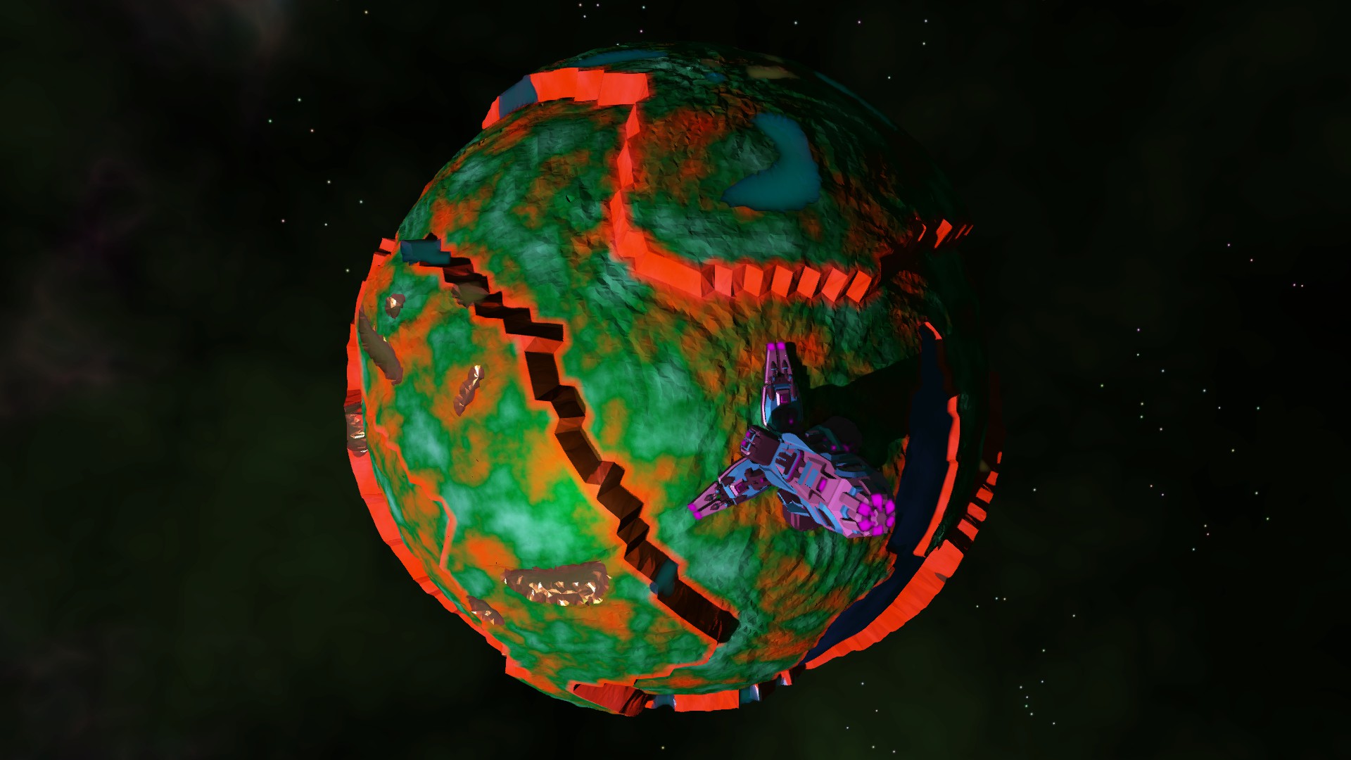
Now that looks pretty. The blues and golds are part of the resource system of Zero Sum Future, and I threw those in also just to show what else you can do with tessellation shaders. Those, of course, are left as an exercise for the reader.