Requirements
As mentioned in the previous post, all modules share the same base. So the first task is to model a core where all individual modules can be extended from. As the game is built on a (flat topped) hex grid, modules must meet two conditions: 1) they must be attachable to their neighbors from six edges and 2) each module, including all additional parts, must fit inside its hex grid cell.
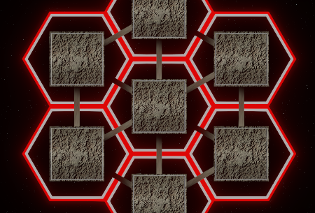
Hexes don’t restrict the module’s base form (so far, I've been using just cubes). As the game uses 2D-physics, only top-down profile matters when it comes to collisions. If you want to know more about hex-grids, there’s a wonderful page with throughout theoretical and practical information: Redblobgames.com
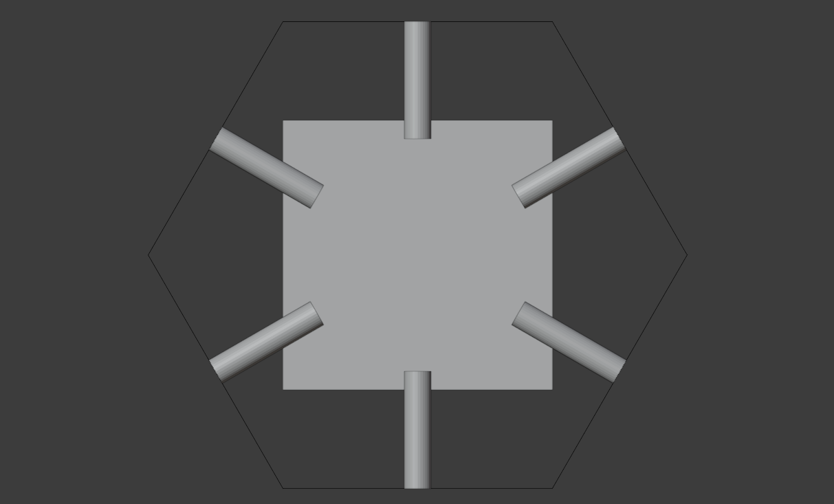
Before starting, I made some reference models to visualize the requirements and to help with a scale. The most important one is a hex that components should never overlap. Additionally, I used dummy objects to represent the size of old modules and connectors.
Building the geometry
Note: I'm using Blender 2.91.0 with default key-bindings. Other versions may differ somewhat.
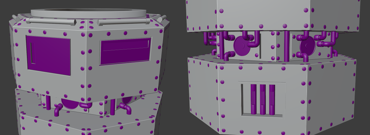
Initially I considered using round modules, but found out that angular forms make the parts bounce more interestingly. As a result, an octagonal shape ended up being a good compromise. So, the top and bottom parts of the model have eight corners (purple), while the smaller middle part, where the connectors will be attached, has six (blue). I’ll cover the actual connector models in the future chapters.
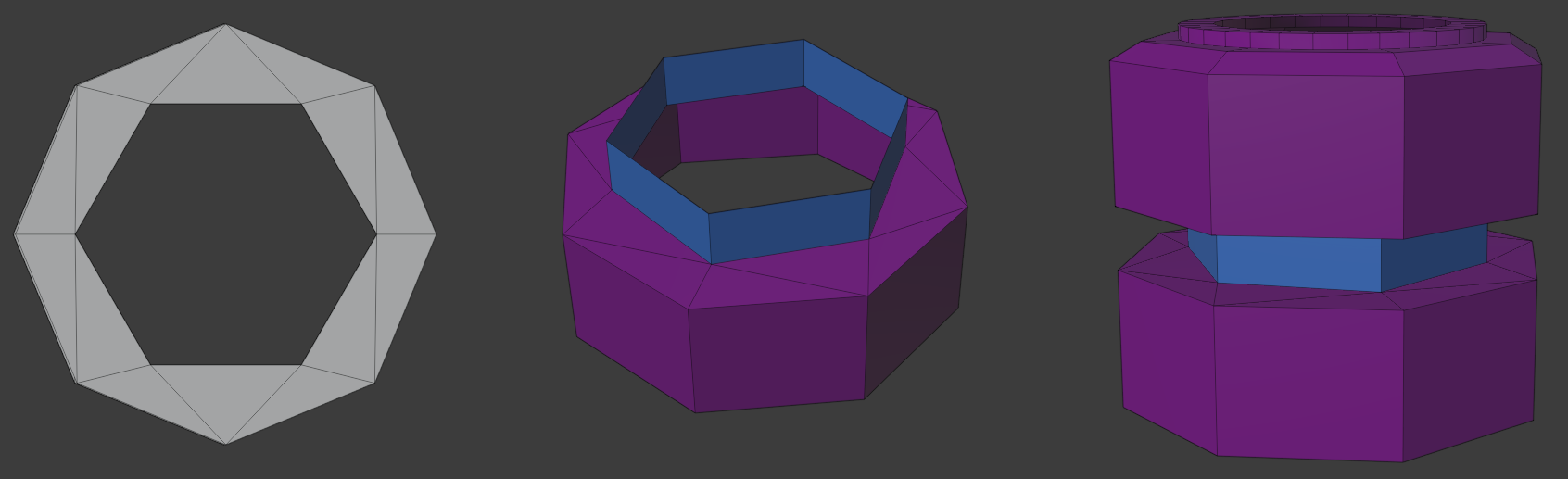
Modelling was quite straightforward: top and bottom are made of eight-segment, open-ended cylinders, while the middle cylinder has only six edges. On the very top (better visible in the image below), slope is made by extruding and scaling, while the circular part is just another open-ended cylinder with a little inset on top. I joined parts together as one object and used "Edge" -> "Bridge Edge Loops" to fill the space between the edges. Module base has open top and bottom which will be later concealed with module-specific parts.
Each module must have lights that indicate the owner of the ship (player's color) and module’s condition (dim light means broken module). So eight tube lights surround the top of the part (colored purple in the image). Additionally, testers have been complaining that when a ship loses modules, it can be hard to perceive its heading because the ship's shape changes. I decided to add a bright arrow-light to indicate the forward direction (colored blue). Hopefully that helps.
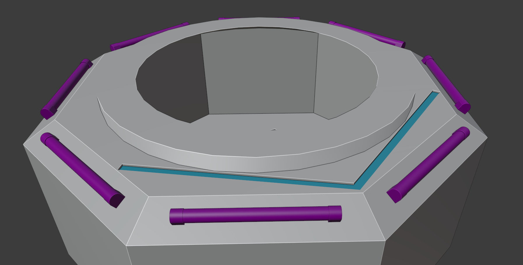
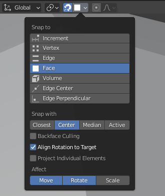
The forward-light is carved into the base mesh with a difference-operator of the boolean-modifier. Tube lights are just cylinders with loop cuts on both ends. where bottoms are flattened to meet the module's surface (later I learned about the shrinkwrap-modifier that might make better topology). The trickiest part was to make the lights' rotations snap onto the sloping surface. Snapping is enabled from the top of the 3D-viewport. I still haven't fully understood how the snapping should be used and it took me several tries to succeed, but these settings seem to work.
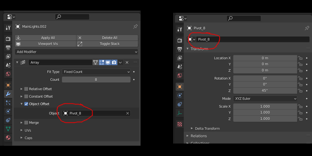
After I had one tube light ready, I used an array-modifier to copy it onto all eight sides. Creating a circular array is quite unintuitive. First, you have to reset the light object’s transform (select object -> ctrl + A -> "All Transforms") and add an array-modifier into it. Then create a separate pivot object ("Pivot_8" in a screenshot) at the desired center point ("Add" -> "Empty" -> "Plain Axes"). In the modifier, set the number of objects (eight in this case), select "Object Offset" checkbox and deselect others, drag the pivot object from outliner to "Object"-slot and finally, select the pivot object and set its rotation. For eight objects, the rotation is 360 / 8 = 45 degrees for a full circle. In this case the rotation is done around the z-axis.
For the future, BagaPie seems like a promising free addon that has a circular array with plenty of options: Gumroad.com.
Beginner’s tip: remember to apply transforms or at least scaling before insetting, beveling, texturing or doing pretty much anything. With non-uniform scaling you’re going to have some weird results. Do this by selecting the object, pressing ctrl + A and choosing "All Transforms".
The hi-poly model needs extra details in order not to look too boring: lots of bolts, one hatch for electric stuff, another one for module-specific mechanics, some pipes for carrying electricity/control information, fasteners for connectors, debug displays to decorate the lower part, … I think this will do for now.
Pipes are made by extruding/insetting common cylinders. I wanted to avoid addons for now in order to learn the basics, so I used the built-in spin-tool (Docs.blender.org) to make the pipe turns. Bolts are squish half-spheres that I first duplicated to fill one side (with alt + d so they reference the same mesh data) and then joined them, applied transforms and used an array modifier in order to replicate them to all sides (similarly to lights). Placing every bolt by hand is actually a good way to give models some early-industrial feel, but since there are going to be a LOT of them, I’ll just copy-paste for now (using some kind of random-functionality would work too, I guess). Hatches are made with standard insetting and extruding. Just make sure to extrude and inset along the face’s normal/surface, not world axis. At first, I didn't (this error can be hard to notice with small details).
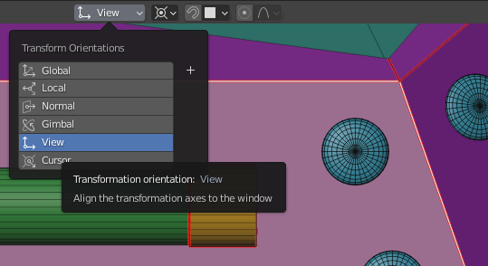
Beginner’s tip: select face and press shift + numpad 7 to align the camera with it (use shift + numpad 4/6 for rolling the view). Select transformation orientation to "View" in order to work in this space. A very useful feature when decorating surfaces that aren't aligned with the xyz-axis.
Assigning color IDs for materials
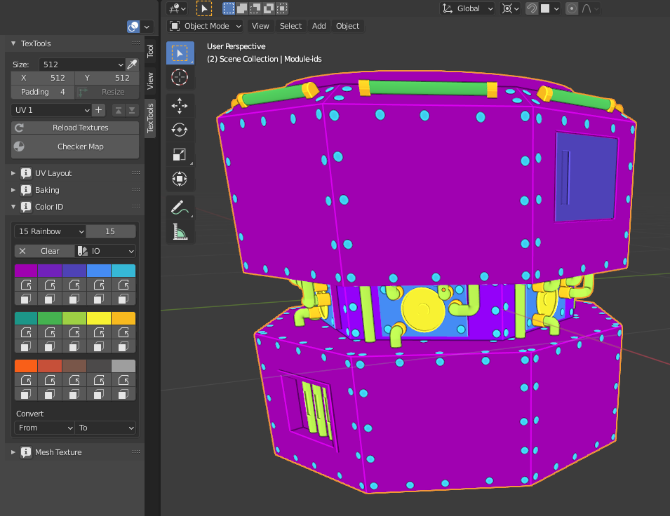
Assigning unique color IDs for different parts of mesh is useful later, when setting materials/textures in Substance. For instance, the base surface will have a specific color ID, steel bolts have another, plastic pipes have yet another one and so forth. I find it easiest to assign colors for separate objects before applying modifiers and joining, but one can also assign them for individual faces. It is practical to define color IDs during UV-mapping, since there’s a free plugin TexTools (Renderhjs.net) to help you with both.
Color IDs for the core model are visualized in the image below. On the left is the UV-editor with TexTools opened (clicking an icon below a color assigns the color for the selected faces).
UV-projection is done after color assignment is ready and the objects are joined as one. Before joining, take a copy of all the objects (use collections to organize them), so you can go back to previous phases in order to fix things. Then apply modifiers, select all objects and join them as one (ctrl + j). Remember to reset the result object's transform.
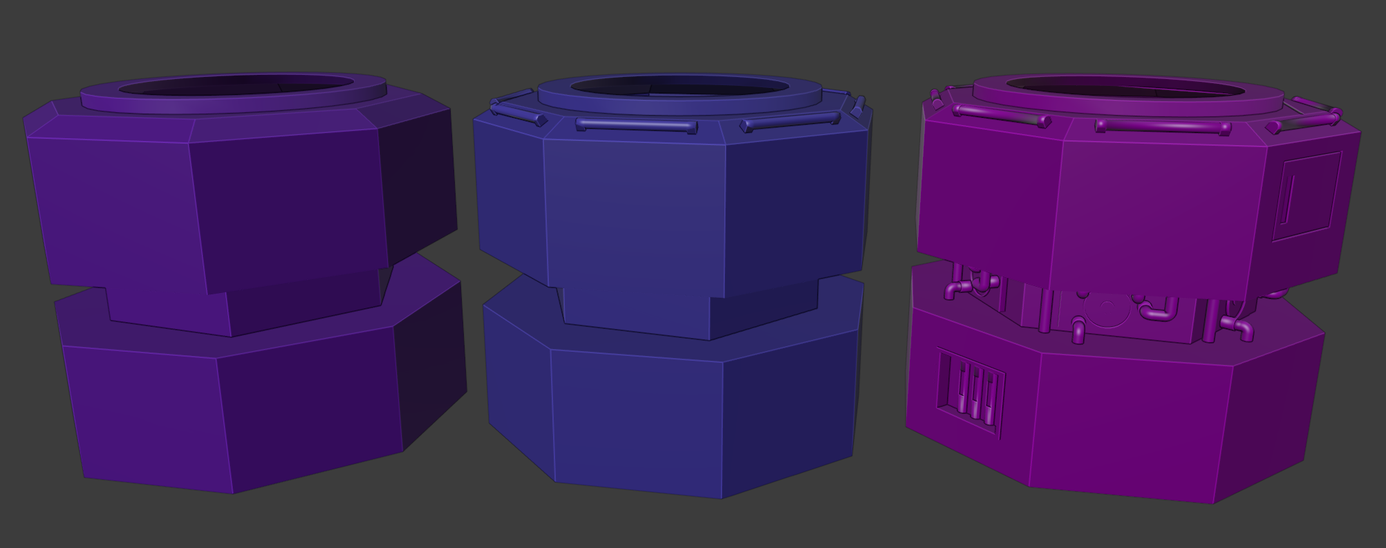
In addition to the above-mentioned color ID-model, I made three models with different levels of detail (LOD): low poly version with only the base form, medium model with simplified tube lights in order to add some depth, and the high poly model with all the details except bolts. Vertex counts are 148, 382 and 19408 respectively. I assigned a unique material for each model so Substance knows to treat them as separate objects.
Optimization of the UV-space usage is a time-consuming task, so I will only perform some trivial things during the first iteration. That is, give more space for upward-facing surfaces since they are the ones mostly visible in a game. Note: the following steps concern only LOD models as they are the ones shown in the game. As the color ID mesh is only used in assigning textures, there’s no reason to waste time optimizing its UV-mapping (just unwrap and use what Blender suggests).
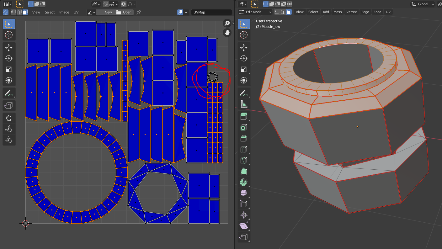
The screenshot below shows the UV-map of the low-poly model. Each model has a unique mapping and the hi-poly model's map is much more complicated, but the same principles apply. Note that downwards-faces (tiny area inside the red circle) are scaled smaller and upwards-faces larger. There is a lot of empty space inside the circular islands that could also be utilized by pinning small islands inside them. That is not the priority right now, however.
Instead of optimizing, my main goal is to prevent the textures getting distorted. I assigned a texture seam (edit mode -> select edge -> "Edge" -> "Mark Seam") on every sharp edge to keep the flat surfaces unstretched. Curved (i.e. more densely tessellated) surfaces took more experimenting; fortunately there are few of them.
Some tips:
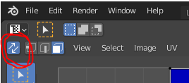
- I prefer to enable syncing between the UV-editor and 3D-viewport. There’s a small icon in the top-left corner of the UV-editor for that.
- While hovering over a face (either in UV-editor or 3D-viewport), L selects all linked faces as well. You can scale selected faces with S. Perform unpack after each adjustment, and REMEMBER TO SAVE before unpacking (the functionality seems to be pretty unstable).
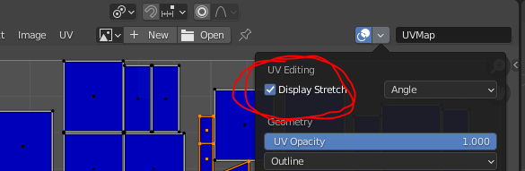
- For keeping texture distortions as small as possible, activate “display stretch” in the UV editing -panel. Blue means no distortion. This helps a lot especially with curved surfaces.
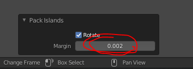
- Leave a small margin between islands when packing them. It reduces texture bleeding in Substance.
Exporting
After texturing I had four models ready for exporting: one with color IDs and three LOD models with unique materials. I have a following checklist to go through before exporting:
- All objects (including the color ID -model) must be positioned and scaled perfectly onto each other.
- All objects' transforms must be reset.
- All LOD models must have a different material assigned to them.
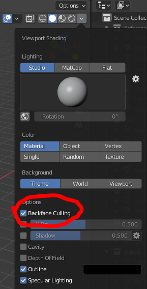
- Remember to check that models look right with backface culling enabled. Doing this now prevents nasty surprises later.
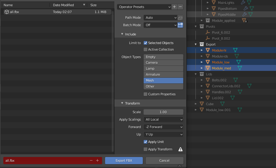
I exported the ID-model into one FBX file (“ids.fbx”) and three LOD models into another one (“all.fbx”). Specific models can be exported by selecting them and setting "Limit to" -> "Selected Objects" in export dialog.
And that’s it. In the next chapter, I will use Substance to give models a more interesting surface than just plain color.
Thank you for reading. And as always, comments, ideas and questions are welcome either in the comment section or by email (mobilelastgames@gmail.com).