Hello,
My name is Dave and today I am going to hopefully talk you through and show you how I model things for Limit Release for those who wish to help, let me first start by saying that because I have spent a considerable length of time researching various ways of modeling in the past this style of modeling is what I like to call "Observational box modeling", essentially the theory behind it is that you model the object based on what what individual shapes the over all object is made up of, break it down into those individual shapes to make it easier to handle and then use normal game development rules to finish off the model, say for instance none of my models have cylinders that are more than 12 sides because normal titles release in today's market normally have cylinder shapes that have between 5-10 sides.

So to get started we first need a program to work with, I use 3d Studio Max and have done for many years now so that is the starting point, 3d Studio Max can be downloaded on a student account from the Autodesk website and will work for a year for free using a student account found in the link below.
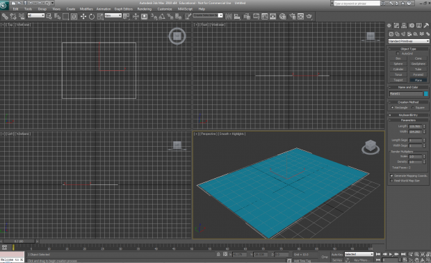
Once you have 3d Studio Max and click on it to start the program you will be greeted by this window when it has fully loaded.
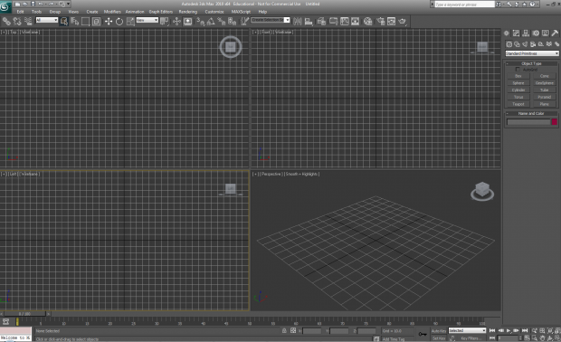
This is the main window for 3d Studio Max that contains all of your essential tools and viewports that control what you see on screen and from different angles, first we will start off by getting some reference of what we want to model, for the sake of this tutorial I will be modeling a standard rifle weapon from the Armored Core 3 era, reference generally is just a fancy term for something you can use to judge scales of things and look at so you do not miss out any details, it can be an image, a video or even a physical thing like a toy or a prop.
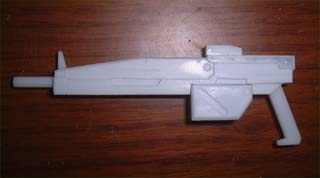
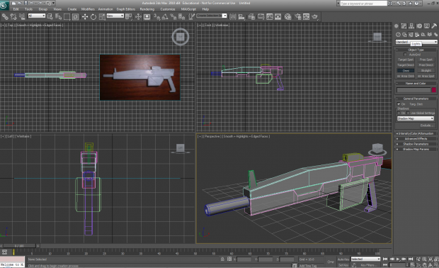
This is my reference that I will be using, first we need to set up 3d Studio Max to be able to begin modeling in comfort and with ease, so lets go about doing that now.
(1-1)
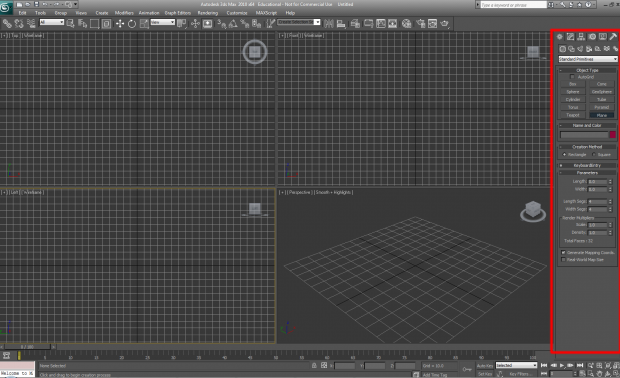
This tool bar I have highlighted in red on the right hand side will be your main focus when modeling as it contains the majority of the tools you will use to create and mold shapes into the shapes you want, click "Plane" to gain the ability to create one flat 'paper' like surface by clicking the left mouse button and then dragging in the "Perspective viewport (bottom right viewport)".
(You can click and drag in every viewport but depending on the window it will angle its self different when being made)
When you are happy with the size let go of the left mouse button and the shape will take the size you dragged it to.
(1-2)
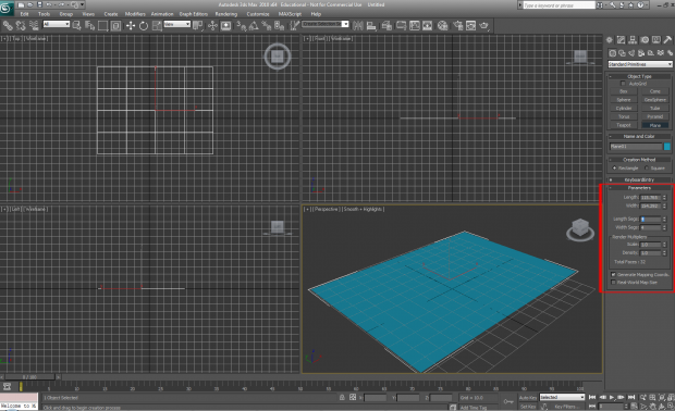
Once the plane has been created in the view port look on the right hand side in the parameters options, the section I have high lighted in red controls how many polygons are in the surface, this is controlled by the length and width segment numbers, the larger number you have in this section the more polygons will be in the model, because we are only putting an image on this surface it does not need to be full of polygons so lower the number to 1, when doing this watch as the wireframe of the surface changes so that there are not as many lines in the object thus reducing the number of polygons.
(1-3)
This is what it should look like when it has had its polygon count reduced, expect to use these parameters for different shapes later on to control your polygon counts wisely.
(1-4)
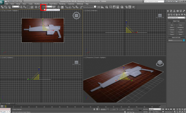
I have then clicked and dragged the image onto the "plane" in the viewport and used the "Scale" tool to resize the plane to allow the image to fit onto it (The Scale tool works by clicking and dragging similar to how you created the original plane but will display a pyramid shape on screen over your object with the X,Y and Z axis on it this allows you to scale the shape you have on those axis by clicking and dragging on the coloured control lines as shown in this image), you may have a problem with image quality in 3d Studio Max, if you do click "Customise" in the top bar running along the entire program located in between "Rendering" and "MAXScript\", then click "Preferences" at the bottom of this drop down menu.
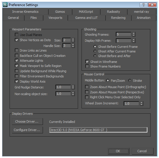
When you have clicked "Preferences" you will be taken to this window, click the "Viewports" tab to allow you access to the viewport options, then as shown in this image click "Configure Driver" this will allow you to set the various options of your visuals in 3d Studio Max.
Make sure in these options that your "Background Texture Size" and "Download Texture Size"`s are set to the maximum they can be by clicking the buttons that have the highest texture resolution on them respectively, 1024 and 512, then restart 3d Studio Max to see the effects it has on textures in the viewport.
(1-5)
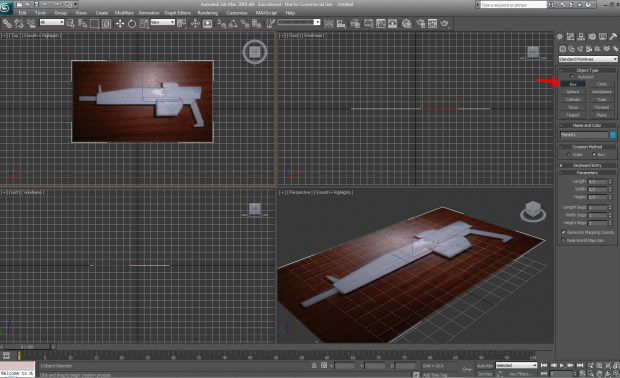
Now lets start getting to grips with getting the basic shapes created, click the box option from the standard primitives menu then click and drag it just like when creating the plane, the only difference will be when you let go and move your mouse it will allow you to scale the height of the box if you click again after getting the height just how you want it the box will stay at that current scale.
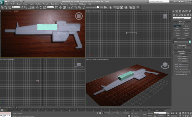
(1-6)
When done it should look like this, now you have box but we need to start getting the shape sorted not just a box so first off press ALT + X to make your box see through, this will allow you to be able to edit things much easier.
(1-7)
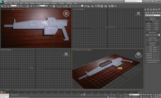
Once ALT + X is pressed your model should be see through as shown in this image, pressing ALT + X again a second time will return it to its none see through state.
(1-8)
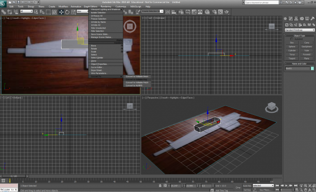
Now to get started properly, right click on the box and click "Convert To >" then from the options that appear in the drop down menu at the side of the "Convert To >" section always select "Convert To Editable Poly", this will give you more tools that will help shape your models in the right hand tool bar that I high lighted and talked about in (1-1).
(1-9)
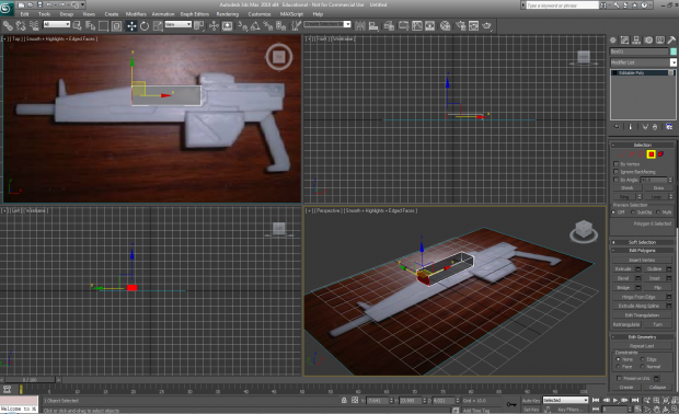
In the new options in the right hand tool bar if you select the yellow high lighted box this allows you to use the "Face select" tool, this will enable you to select any face you click or multiple faces, then use other tools to edit just the areas you have selected.
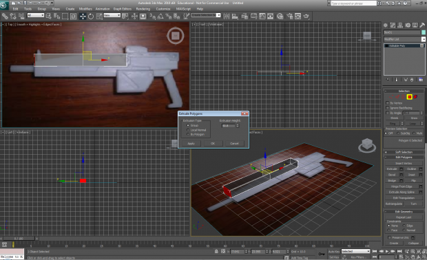
(2-0)
By clicking the small box next to the "Extrude" button in the "Edit Polygons" menu this allows you to extrude polygons outwards from the face you selected and allows you to adjust the size of the extrude by changing the "Extrusion Height" number.
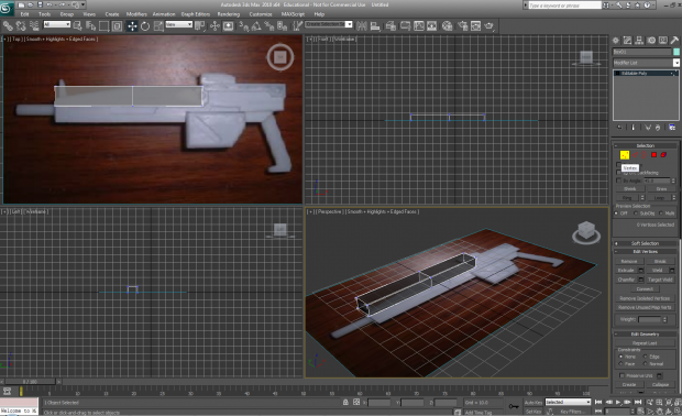
(2-1)
By clicking on the "Vertex" option represented by 3 dots in the selection menu in the right tool bar from (1-1) you will be able to move individual points (Vertex`s) in the model which will give you more control of what your model looks like.
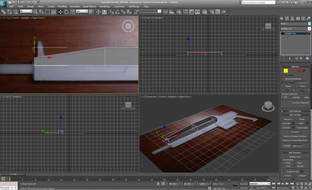
(2-2)
Here In this image I have moved the vertex`s for the top of the extruded box using the "Move" tool located next to the "Scale" tool in the top bar referenced in (1-4) and is represented by a icon of arrows pointing up,down,left and right, by moving Vertex like this we can start to get more shape into this box.
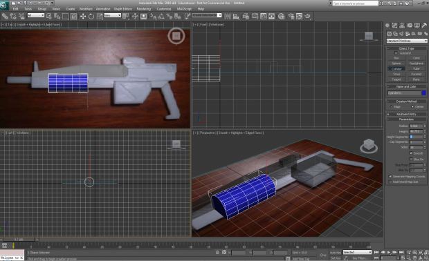
(2-3)
As I stated before when creating new shapes you will be able to control the number of polygons in a shape, in this cylinder that I just dragged out after shaping the top of the rifle there are way too many sides and height segments, so its time to lower those using what we know from (1-2).
(2-4)
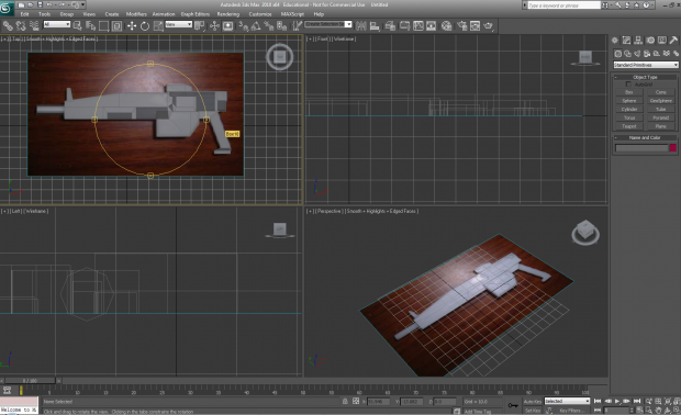
I changed the number of height segments to 1 and the number of sides to 8 for the cylinder and then once it was scaled correctly I repeated the previous steps with the rest of the rifle to make the entire body of the weapon as featured in this image.
(2-5)
After scaling the entire body of the weapon to look accurate I then used the face tool to select all the faces that are definitely not going to be rendered and deleted them.
(2-6)
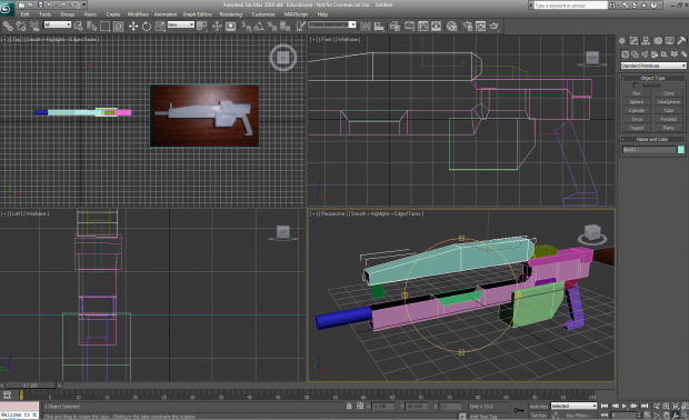
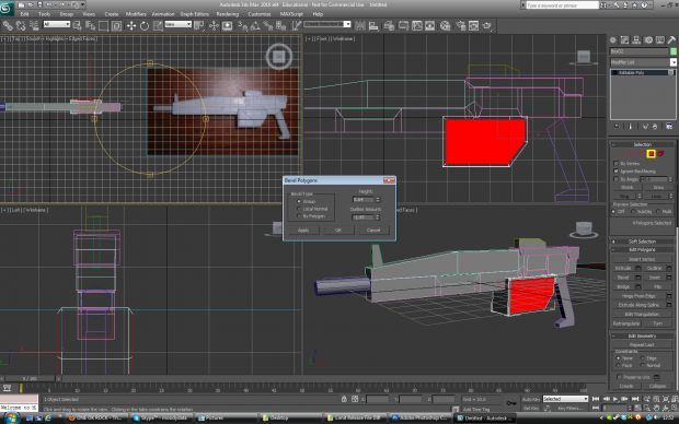
To change the colour of the model press the M key to bring up the Material window, you can then select a base texture just for the sake of the model not looking too goofy and click "apply material to mesh" in the material window menu to turn your model grey, I then went back into edit polygon mode and started to make the raised surfaces with angles to them by selecting the faces I wanted and then selecting the "Bevel" option and changing the height and outline numbers to match the look of the rifle.
(2-7)
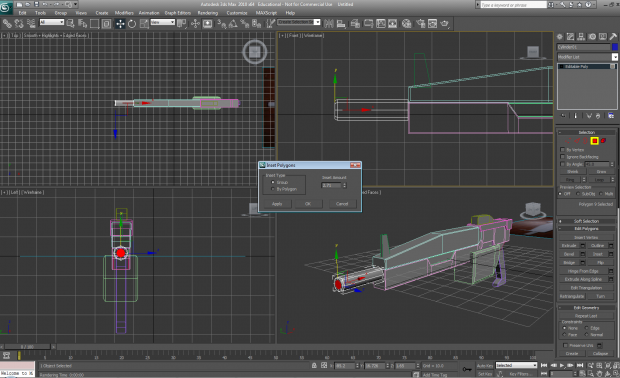
After going along the surface of the weapon and beveling all the faces on the sides of the model to give it edges I then used the face tool to select the top face of the cylinder and used the "Inset tool" to create a smaller face inside of the original, when extruded inwards this looks like a gun barrel.
(2-8)
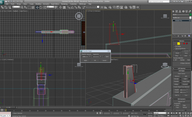
Almost done now! to finish off the model I select the edges of certain sections of the model (Not all of them) and use the "Chamfer" tool, this allows you to create supporting lines along side the original that gives you sharper edges when rendering.
(2-8 Extended)
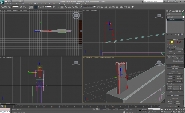
I took the entire body of the gun and chamfered the edges that had been created by the bevel, and then chamfered the supporting edges with smaller supporting edges to give a much sharper look.
(2-9)
Apart from "Floats" which can be used to give more details this model is ready to be baked, at step (2-7) after beveling the faces I wanted I would normally stop and have that version of the model be the low polygon version to be used in engine, any chamfered versions get used to bake normal maps onto the low polygon model so that the edges can stand out more.
I normally use floats to give the impression of more detail that you do not need to model into the actual original model its self, they just float above it thats why they are called floats, you can find information about floats online.
Essentially that is it for this tutorial, I hope this has helped.


Do you want also custom made stuff or has to look directly like the models on pics?
The animation will be using mostly parts and enemies from the games, there will only be small inclusions of custom content for reference reasons.
Well thanks for instructions, gota still familiarize myself with 3d max again so it take time, but got no templates to work on, can you send me some? Also is this program compatible with UDK, in importing character animations?
A good place to get some content to look at and reference is the Armored core models off of the 1999.co.jp/eng website, direct link included here
1999.co.jp
plenty of pictures and weapon packs as well as the assembly guides included.
Thanks
3DS Max is compatible with UDK, you export the model along with the animations out as an FBX and import them into UDK, it is a rather long process but you can start by getting the static meshes into the engine to see how they work.
UDK is free to download and it is a bit tricky to get the grasp of at first, there are tutorials out there and i can direct you to a few (maybe i should start a forum thread up on this)
No one else should need UDK apart from me to be honest as this is all one giant modeling collaboration at the moment.
Actually, I have some own personal ambitions to do with the udk, that's why I wanted to know.
Wait so you essentially used me to obtain information about 3d studio max?
No, I wanted to also help, but lately unable to make use of computer to even do anything.